


32
COMPONENT DESCRIPTION
UNLOAD
Line Pressure
Dry Side
Wet Side
LEGEND
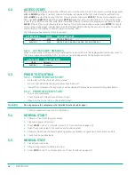
FIGURE 3-5.
108MM 15-50hP VFD MPC CONTROL SYSTEM (UNLOAD) R00
An unload condition occurs when the VFD Target pressure set point is achieved with an additional 10 psi
(0.7 bar) overshoot. The microprocessor will change the state of the blowdown solenoid valve sending
control air to shut the inlet valve. The minimum pressure valve will transition to the checked position
isolating line pressure and sump pressure. The same control air pressure that is holding the inlet valve
closed is also venting the pressure in the sump to atmosphere to reduce the power consumption.
SHUTDOWN
CAUTION!
If the compressor operates in the unloaded condition for the pre-programmed “Run on Time” the
compressor will enter a standby condition and stop. When demand for air increases, the compressor will
restart automatically and provide the required air capacity to match the demand.
Manual shutdown can also take place. If an operator presses the stop push-button, the system will go into
an unload condition and blowdown prior to completely shutting down.
CAUTION!
The operator should use the E-Stop button for emergencies only!
3.8.1
INLET AIR FILTER
The inlet air filter removes contaminants from the air entering the compressor system through the inlet
control valve. It is a heavy duty two-stage air filter which includes a primary filter element and secondary
safety filter element to prevent dust from entering the system during routine maintenance.
3.8.2
INLET CONTROL VALVE
The inlet control valve is the main control for air capacity within the air compressor. The valve is initially
opened at start-up by suction created from rotating screws in the compressor unit, and is forced closed for
the predetermined load delay time, allowing the main motor to come up to speed and sump pressure to build.
An air signal from the pressure regulating control valve will modulate the
poppet disc when air demand is
low (non-VFD). Upon shutdown, the
poppet disc
closes to eliminate reverse airflow from the compressor to
prevent the compressor unit from turning backwards. The inlet valve is mounted directly to the compressor
unit inlet.
Summary of Contents for UD Series
Page 6: ...vi About This Manual ...
Page 12: ...4 Introduction ...
Page 42: ...34 Component Description ...
Page 52: ...44 Operation ...
Page 66: ...58 Troubleshooting ...
Page 74: ...66 Parts Catalog 8 5 COMPRESSOR FRAME AND DRIVE ASSEMBLY Figure 8 1 AS801 25UD 50UD VFD R00 ...
Page 76: ...68 Parts Catalog 8 6 CONTROL ASSEMBLY OPEN Figure 8 2 1072190415 609 R00 ...
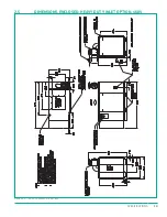
Page 78: ...70 Parts Catalog 8 7 STARTER ASSEMBLY ENCLOSED Figure 8 3 AS802 405060 PANEL R03 ...
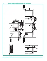
Page 94: ...86 Parts Catalog 8 15 COOLING ASSEMBLY AIR COOLED Figure 8 11 AS804 50UDAC INLINE R00 ...
Page 100: ...NOTES ...
Page 101: ...NOTES ...