


31
COMPONENT DESCRIPTION
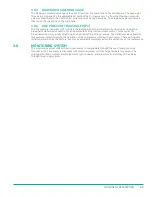
FULL-LOAD
Line Pressure
Dry Side
Wet Side
LEGEND
FIGURE 3-4.
108MM 15-50hP VFD MPC CONTROL SYSTEM (FULL LOAD) R00
After the initial start-up and the load delay has expired, the solenoid valve will shut off the blowdown circuit,
allowing the sump pressure to come up to operating pressure. During this time, no control air will be flowing
to any major components. As the sump pressure reaches the set point of the minimum pressure valve, air
flow to customer’s process will start. The outlet pressure to the customer’s process is monitored and will
control the blowdown when needed. Sump pressure and line pressure are displayed on the control panel to
visually monitor the status of the compressor. Until the customer’s process achieves the set pressure, the
compressor will run in the full-load condition.
Summary of Contents for UD Series
Page 6: ...vi About This Manual ...
Page 12: ...4 Introduction ...
Page 42: ...34 Component Description ...
Page 52: ...44 Operation ...
Page 66: ...58 Troubleshooting ...
Page 74: ...66 Parts Catalog 8 5 COMPRESSOR FRAME AND DRIVE ASSEMBLY Figure 8 1 AS801 25UD 50UD VFD R00 ...
Page 76: ...68 Parts Catalog 8 6 CONTROL ASSEMBLY OPEN Figure 8 2 1072190415 609 R00 ...
Page 78: ...70 Parts Catalog 8 7 STARTER ASSEMBLY ENCLOSED Figure 8 3 AS802 405060 PANEL R03 ...
Page 94: ...86 Parts Catalog 8 15 COOLING ASSEMBLY AIR COOLED Figure 8 11 AS804 50UDAC INLINE R00 ...
Page 100: ...NOTES ...
Page 101: ...NOTES ...