background image

DX - ISOBUS


C

ALIBRATION OF THE


 WEIGHING DEVICE


C1 


N

AME

 :


T

RAINING 

D

EPARTMENT


D

ATE

 :


2019.09 

P

AGE

 :


12/55 

R

ÉFÉRENCE

 :


T

ECHNICIAN 

O

PERATING 

M

ANUAL 

DX


ISOBUS 

I

ND 

01 


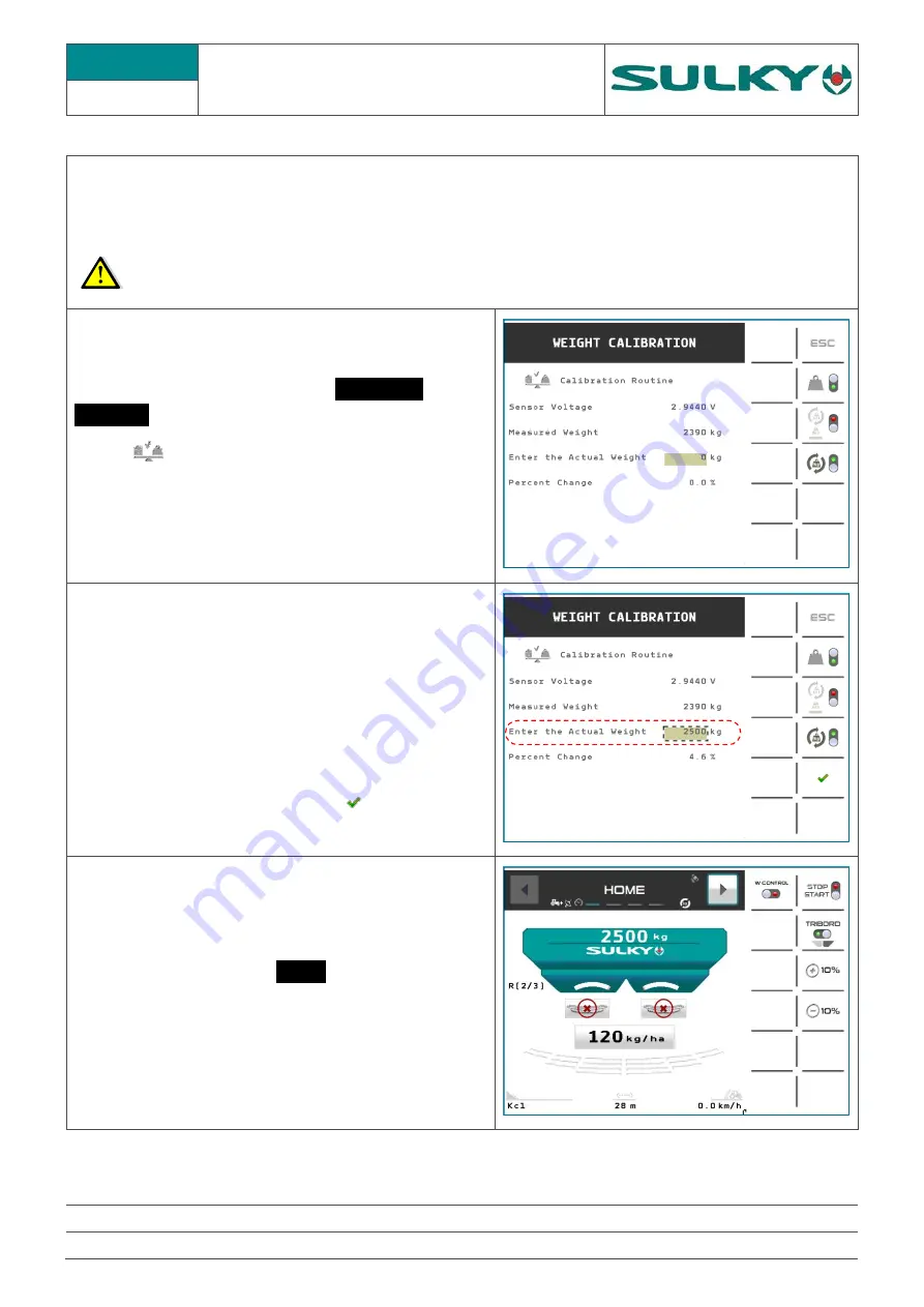
The weighing device allows a tolerance margin of 3%. If you notice a weight difference between the control 

unit information and the real weight, you can calibrate the weighing device sensor. To calibrate the weighing 
device sensor follow the procedure below. In order to be able to calibrate the sensor, load a known weight into 
the hopper. (The weight must be a minimum of 1000 kg).   


The reference weight must be accurate in order to obtain a good result. 


On the universal terminal, access the 

ADVANCED 

SETTINGS

 menu 

Select 


Weight calibration  

Enter the PIN code 1234 and confirm. 


Enter the Actual Weight

 and select the 

corresponding field 


The software calculates the error percentage. 


Confirm the calibration with the key


Press 

ESC

 and return to the 

HOME

 page 

The weighing device is calibrated


Summary of Contents for DX ISOBUS

Page 1: ... 401 018 01 EN DIS Sulky Burel Les Portes de Bretagne P A de la Gaultière 35220 Chateaubourg France Adresse Postale Sulky Burel CS 20005 35538 Noyal sur Vilaine cedex France Tél 33 02 99 00 84 84 E Mail info sulky burel com www sulky burel com ...

Page 2: ...CIAN OPERATING MANUAL DX ISOBUS IND 01 CONTENTS PAGE NO I SPECIFICATION SHEETS 4 43 II DIAGNOSTIC PROCEDURES 44 51 III START UP 52 53 To comply with the instructions for safety and use refer to the instruction manuals corresponding to the fertilizer spreader and the electronic console ...

Page 3: ...settings 11 C1 Calibration of the weighing device 12 C2 Angle sensor of the weighing device 13 C3 Weighing blades check 14 C4 Replacement of weighing blades 15 16 C5 Pre tensioning spring dimension inspection 17 C6 Weighing device sensor 18 19 D1 Electrical application rate actuators 20 22 D2 Tribord actuator 23 25 D3 Stop Go actuators 26 27 D4 Shutter sensors 28 D5 ECU Electronic Control Unit 29 ...

Page 4: ...DX ISOBUS GLOBAL VIEW A1 1 NAME TRAINING DEPARTMENT DATE 2019 09 PAGE 4 55 RÉFÉRENCE TECHNICIAN OPERATING MANUAL DX ISOBUS IND 01 ...

Page 5: ... wiring bundle GPS antenna ISOLINK 683845 CAN ECU connection box Connection box 721989 Cable 721990 Tribord actuator 082502 Stop Go Left hand actuator Shutter opening 013515 Stop Go Right hand actuator shutter opening Left hand shutter opening ILS sensor 083912 Right hand shutter opening ILS sensor Left hand application rate actuator 082501 Right hand application rate actuator Weighing sensor 0839...

Page 6: ...S MALE PLUG ECU FEMALE SOCKET PIN COLOUR FUNCTIONS PIN COLOUR FUNCTIONS 1 Black White 0 V 60 A 1 Red 12 V 2 Blue 0 V 25 A 2 Brown 12 V 3 Red Brown 12 V 60 A 3 White 0 V 4 Purple 12 V 25 A 4 Purple Contact ECU 5 Link to pin number 4 Relay control of terminaison 5 Green CAN Lo 6 Yellow CAN Hi 6 nc 7 Black 0 V 7 nc 8 Yellow CAN Hi 9 Green CAN Lo ...

Page 7: ...DX ISOBUS ECU CAN CONNECTION BOX A3 NAME TRAINING DEPARTMENT DATE 2019 09 PAGE 7 55 RÉFÉRENCE TECHNICIAN OPERATING MANUAL DX ISOBUS IND 01 ...

Page 8: ... case the following settings must be checked A The space between the tip of the agitator A and the shutter must be 10 mm This distance may not be exactly 10 mm the most important thing is that the two agitators have the same dimension for example 12mm To adjust the distance of an agitator tip simply loosen the screws and move the tip on its support B The agitator tip sweep must be symmetrical in r...

Page 9: ...m lever Remove the flow reducers if they are mounted Place a Ø 34 mm round bar in the shutter opening Then close using the lever until the shutter comes into contact with the Ø 34 mm rod Under these conditions the index of the application rate lever must be at mark 35 If this is not the case the index is mounted on slot and therefore it must be moved in front of mark 35 If necessary fit back flow ...

Page 10: ...lect Actuators Sensors Enter the PIN code 1936 and confirm Using display the page Actuator Setup Press The terminal is displayed Actuators Adjusted Application rate electric actuators The index of the application rate levers must be on mark 35 If this is not the case the lower attachments of the actuators must be adjusted presence of adjustment slots At the minimum travel of the actuator rod retra...

Page 11: ...tter guide is too tight it can cause blocking of the shutter during its hydraulic opening before it comes to a stop with control In this case you must free up a gap with screws Check with the spreader under load and leave a gap of approximately 1 mm between the bowl and the shutter For easier access to the upper screw it is advisable to remove the disc ...

Page 12: ...device sensor follow the procedure below In order to be able to calibrate the sensor load a known weight into the hopper The weight must be a minimum of 1000 kg The reference weight must be accurate in order to obtain a good result On the universal terminal access the ADVANCED SETTINGS menu Select Weight calibration Enter the PIN code 1234 and confirm Enter the Actual Weight and select the corresp...

Page 13: ...ement enables the weighing device to be corrected depending on the angle of the machine An incorrect calibration distorts the display of the weight Angle sensor calibration Position the spreader perfectly level both front rear and left right On the universal terminal access the ADVANCED SETTINGS menu Select Actuators Sensors Enter the PIN code 1936 and confirm Using display the page Angle sensor O...

Page 14: ... the weight displayed on the console for a similar weight is highly random you must check that there is no friction or foreign bodies between the weighing device frame and the spreader chassis If there is friction on the frame the tightening of the screws and the condition of the spring blades must be checked Screws are tightened to 18 daN m ...

Page 15: ...recommended that you have a socket for size 14 hexagon socket screws e g reference STM 14 1 Place a nut on the pressure screw to compress the pre tensioning spring 2 Remove the strain gauge 3 Remove the 2 safety stops 4 Unscrew the 16 x 65 stainless steel screws on the triangle side 5 Remove the triangle The weight of the triangle is 90 kg Provide appropriate handling equipment 6 Remove the blades...

Page 16: ...ot tighten them 8 Caution At the upper level on the spreader side There is a shim only under the spring blades There are no shims between the top of the blades and the support 9 Place the triangle and put the screws back without tightening them 10 Centre the triangle so there is no friction and secure the screws to 18 daN m 11 Put the safety stops back 12 Put the weight indicator into position and...

Page 17: ...ght indicator with the machine unhitched 2 Adjusting the pre tensioning of the spring If the dimension of the spring is not correct you must adjust the clamping screw at the weight indicator to compress or release the spring a Place a nut on the pressure screw to compress the spring to height 67 71 mm b Unscrew the cone point set screw c Adjust clamping screw until it comes into contact with the w...

Page 18: ...ue wire WIRE COLOUR FUNCTION BROWN 5 V BLUE 0 V YELLOW GREEN V SIGNAL MV BLACK 0 V SIGNAL GREY SCREEN 3 Weighing device settings On the universal terminal access the ADVANCED SETTINGS menu Select Actuators Sensors Enter the PIN code 1936 and confirm Using display the Weigh Cell page Tare point and High point are the weighing device calibration values In case of a malfunction of the weighing device...

Page 19: ...nsor the spreader must be unhitched b Place a nut on the pressure screw to compress the spring so there is no strain on the weighing beam c Completely disconnect the weight indicator in the connection box and uncouple the grey wire from the blue wire d Check the values opposite The weighing device sensor is considered to be compliant if it meets all these indications BRAND SENSOR VISCHAY R BETWEEN...

Page 20: ...vel in mm Actuator Reference 082501 These actuators have a 130 mm travel with limit switches and an ILS position sensor The ILS sensor sends 2 pulses mm of travel Thus for 130 mm of travel the actuator sends 260 pulses They are powered by 4 wires WIRE COLOUR FUNCTION RED POWER SUPPLY BLUE WHITE ACTUATOR SIGNAL ILS SENSOR POSITION SENSOR BLACK 0 V SIGNAL 2 Display of malfunction alarms If there is ...

Page 21: ...isplays Blocked 4 Checking the positioning of the actuators The consistency between the application rate lever mark and the indication on the screen can also be checked Only check between marks 20 and 70 Tolerance is of 1 graduation If the actuator pulses are returned correctly but there is an offset in the graduations please perform a calibration See Sheet B3 Right hand application rate actuator ...

Page 22: ...wer supply and a pulse counter Connect a or power supply on the red and blue wires the rod will extend or retract There is a limit switch On the 2 other wires black and white it is possible to count the pulses with a specific counter e g Omron H7EC etc There should be 260 pulses for a complete extension or retraction of the rod It is also possible to check the actuator motor by measuring the resis...

Page 23: ...nce 082502 These actuators have a 40 mm travel with limit switches and an ILS position sensor The ILS sensor sends 2 pulses mm of travel Thus for 40 mm of travel the actuator sends 80 pulses They are powered by 4 wires WIRE COLOUR FUNCTION RED POWER SUPPLY BLUE WHITE ACTUATOR SIGNAL ILS SENSOR POSITION SENSOR BLACK 0 V SIGNAL 2 Programming On the universal terminal access the ADVANCED SETTINGS men...

Page 24: ...rom the HOME menu make sure that the shutters are closed Access the ADVANCED SETTINGS menu with Select Diagnostics And press the key To check an actuator perform a complete extension of the rod 80 impulsions 2 and a 40 mm stroke should be obtained If there is a fault the screen displays Blocked Not available on DX Tribord actuator extension control Not available on DX Not available on DX Actuator ...

Page 25: ... Connect a or power supply on the red and blue wires the rod will extend or retract There is a limit switch On the 2 other wires black and white it is possible to count the pulses with a specific counter e g Omron H7EC etc There should be 80 pulses for a complete extension or retraction of the rod It is also possible to check the actuator motor by measuring the resistance between the blue and red ...

Page 26: ...it switches They are specific fast travel actuators for the Stop Go function They have 4 wires but only 2 are connected A 220 Ω resistance is fitted between and on each actuator It allows to create an electrical charge on the circuit Some alarm when opening the shutter can appear in case of wrong resistance see below WIRE COLOUR FUNCTION RED POWER SUPPLY BLUE WHITE NOT USED BLACK 2 Display of malf...

Page 27: ...ction of the rod An electricity consumption of between 0 1 and 0 4 A should be seen If there is a fault the screen displays Blocked 4 Electrical control Using a direct current power supply create a or supply on the red and blue wires the rod will extend or retract Right Stop Go actuator Left Stop Go actuator Actuator status Ok Run Blocked Actuator status Ok Run Blocked Min alarm threshold I measur...

Page 28: ...to check the opening and closing of the shutters Sensor reference 083912 2 Checking a sensor The magnet is facing the sensor check the continuity R 100 Ω between the blue and the brown wires The magnet is no longer facing the sensor open contact No continuity On assembly the air gap must be 5 mm max The tip of the sensor must be allowed to jut out by 1 to 2 cm Note The sensors are also used for co...

Page 29: ...munication with the ISOBUS ISOLINK 2 Alarm display When the CAN connection is interrupted or the spreader is not connected the alarm opposite is triggered 3 Diagnostic LEDs The ECU is fitted with diagnostic LEDs MARK NAME COMMENTS POWER RED WHEN ECU IS ON CAN FLASHES RED CAN CONNECTION OK STEADY RED NO CAN CONNECTION LED A ROD EXIT LED B ROD RETRACTION OP 1 LEFT APPLICATION RATE CONTROL OP 2 NOT U...

Page 30: ...CTION 3 6 YELLOW CAN HI 4 5 GREEN CAN LO 5 4 PURPLE ECU CONTACT UT ON 12 V UT OFF 0 V 7 BLACK 0 V ECU ET POWER 8 3 BLUE 0 V POWER 9 2 BROWN 12 V PERMANENT ECU ET POWER 10 1 RED Comments The purple and black wires provide the control of the board lighting but it also requires a 12 V power supply coming from the brown wire or the red wire If the blue wire and or one 12 V wire red or brown is cut off...

Page 31: ...E 2019 09 PAGE 31 55 RÉFÉRENCE TECHNICIAN OPERATING MANUAL DX ISOBUS IND 01 Access the ADVANCED SETTINGS menu with Select Diagnostics ISOLINK software version ECU software version Control and diagnosis for the various actuators Initialization actuators control ...

Page 32: ...coder RIGHT RATE No information from the coder SPEED LOW Risk of over application SPEED HIGH Risk of over under application LEFT CHUTE Not used RIGHT CHUTE Not used STOP GO LEFT Current safety STOP GO RIGHT Current safety HOPPER EMPTY Weight 20 kg TANK LOW LEVEL Weight 200 kg TRIBORD LEFT ACTUATOR PROBLEM Not used TRIBORD RIGHT ACTUATOR PROBLEM No information from the coder PTO RPM LOW Not used PT...

Page 33: ... 0035 and confirm Press Machine Option Read the machine type Press ESC pour exit b Weighing coefficients From the ADVANCED SETTINGS page select Actuators sensors Enter the PIN code 1936 and confirm Using the key to display Weigh Cell Retrieve the values Tare point et High Point Press ESC to exit c Task Controller Parameters From the ADVANCED SETTINGS page select Technician Enter the PIN code 1936 an...

Page 34: ...the name of the fertilizer and its T factor Press ESC Select Spread Width Setup Retrieve the product values Width Blades Press ESC Repeat the operation for each product that you want to save f Regulation and use of flow rate reducers From the CMS 104202 rev 51 software version From JOB SETTINGS page press or depending of machine profil Retrieve the setting of the line Regulation Press ESC g Manage...

Page 35: ...aight Line Dual Rate Control YES NO Connector Type Three point Piton Sections offset X m Y m Spread Length m Time On ms Time Off ms d HISTORY Work area ha Weight Spread Tonnes Working Time Hours e PRODUCT NAMES T FACTORS WIDTH SETTINGS Product names T Factors Width Blades m 12 18 18 28 28 36 m 12 18 18 28 28 36 m 12 18 18 28 28 36 m 12 18 18 28 28 36 m 12 18 18 28 28 36 m 12 18 18 28 28 36 m 12 18...

Page 36: ...lay loss electrical actuator control problem However it is preferable to retrieve data before the reset Please retrieve data before performing a RESET Access the ADVANCED SETTINGS page Select Factory Enter the PIN code 0035 and confirm Press Reset Factors The terminal displays Are you sure Confirm with the key Following the RESET The Universal Terminal reloads the Object Pool Following the RESET t...

Page 37: ...rial number 18AC09105 and 18AE09104 and from Isolink version CMS104 002 rev 51 Press ESC to exit b Angle sensor weighing coefficients i Angle sensor With the spreader connected position the spreader level before calibrating the angle sensor From the ADVANCED SETTINGS page select Actuators Sensors Enter the PIN code 1936 and confirm Scroll through the ATUATORS SENSORS menu with to display the Angle s...

Page 38: ...achines Straight line W Control machines Curve Only for compatible terminals e g Quartz 800 For other terminals use Straight line At mark tick if it is Dual Rate Control Check the following fields Connector Type Sections offset X Front rear et Y left right Spread Length Depth of sections Time On Straight line 1000 ms Curve 2000 ms Time Off Straight line 3000 ms Curve 2000 ms Press ESC to exit d Ar...

Page 39: ... correction RDS Km h Add Check Area Press ESC to exit With ECU version CMA106004 and CMA106009 From ECU versions CMA106010 or CMS113006 e Product names T factors width settings Access the JOB SETTINGS page with the key Select Fertilizer Selection Display the list of products by pressing mark to choose a position for saving and confirm Press mark to enter the name Press to enter the T factor Press ...

Page 40: ... flow rate reducers From the CMS 104202 rev 51 software version From JOB SETTINGS page press or depending of machine profil Select the setting of the line Regulation Press ESC g Management mode of section control Only for machines using the profile WPB DX W CONTROL From the JOB SETTINGS page select Select the setting of the line W Control S G Press ESC to exit ...

Page 41: ...mode Normal use DYNAMIC mode in automatic activation The must be displayed in the black banner and it should not include the keys or on the HOME page Use with a feed hopper DYNAMIC mode in manual activation The key is used to activate or deactivate the Dynamic correction Settings To select the calibration mode go to the ADVANCED SETTINGS page and press Weigh cell Calibration Enter the PIN code 123...

Page 42: ... complete At work the keys allow to activate or deactivate the correction of the factor T Display again the ADVANCED SETTINGS page and select Weigh Cell Calibration Enter the PIN code 1234 and confirm Push the button to hide the key from the HOME menu The indicator turns red as opposite Press and return to the HOME page Back on the HOME page the key has disappeared Make sure the symbol is displaye...

Page 43: ...date files The USB stick should have a folder named fileserver In which there should be a sub folder named Until ISOLINK version CMS104 002 rev19 sulky From ISOLINK version CMS104 002 rev 30 MCMC0511 Copy the Updates cms folder and paste it in the sulky or MCMC0511 folder Do not change the name of the file 2 Transferring files to the Universal Terminal Once the USB stick is inserted into the termi...

Page 44: ... for Updates Where there are several versions on the File Server select the correct one by pressing mark Launch the update by As the minutes go by the screen displays the different stages Data writing Software loading Objet Pool loading ECU reprogramming The Sulky interface then disappears from the terminal and the updated object pool reloads 4 Checking the version The version of ISOLINK may be ch...

Page 45: ...O DIAGNOSTIC PROCEDURES PAGE NO diag 1 1 Difference in the weight display 46 diag 2 2 No weight display 47 diag 3 3 Application rate difference between left hand side right hand side 48 diag 4 4 The application rate electric actuator s does do not move 49 diag 5 5 If there is an application rate difference 50 diag 6 6 The Tribord does not work 51 ...

Page 46: ...e triangle is in contact with the frame Check the condition of the weighing blades Sheet C3 The blades are intact Check tightness Some blades are broken Replacement of weighing blades Sheet C4 Calibration of the weighing device Sheet C1 Ok Make sure the user performs the tare correctly Check that the weight indicator is firmly attached to the frame Check the dimension of the pre tensioning spring ...

Page 47: ...k the power sup ply at the weight indi cator terminals 5 00 V Sheet C6 1 No weight indicator supply voltage Replace the connection box and perform an angle sensor calibration Sheet A2 Sheet C2 Supply voltage OK Check the weight indi cator Sheet C6 2 Replace the weight indicator and perform a calibration of the weighing device Configure the average values by default Empty the spreader perform the t...

Page 48: ...w rate reducers are using control that well place on both side Sheet Not 1 Check the settings of the application rate agitator Sheet B1 Mechanically check the calibration of the shutters at mark 35 Sheet B2 Set the electric actuators to mark 35 Sheet B3 Check if the shutter slides freely Sheet B4 Check if the Stop Go actuators work correctly NO Reverse the electric actuators in the connection box ...

Page 49: ...or both Only 1 actuator Check in the DIAGNOSTICS menu Sheet D1 Reverse the actuators in the connection box The faulty electric actuator still does not work Replace the actuator Inversion of the phenomenon Replace the connection box Sheet A3 Both actuators are faulty Ensure that the selected Regulation mode is appropriate Sheet Not 1 Check the presence of a forward speed Check the programming of th...

Page 50: ...r W Control automatic management check the parameters of the Task Controller overlap percentage opening closing delays etc Make sure of the use or not of a reducer Not 1 sheet Ensure the T factor evolves activation of dynamic mode Sheet F3 5 Make sure the weighing device is accurate Checks on the spreader Make sure the user complies with 540 rpm pto Make sure the shutters are not clogged Make sure...

Page 51: ...THE TRIBORD DOES NOT WORK The Tribord does not work Do you have access from the HOME menu YES Check the presence of 12V or 12V between the red wire and the blue wire of the Tribord actuator when it is activated Sheet D2 OK Replace the actuator No power supply Replace the connection box Sheet A3 NO Activate the Tribord in the Settings menu Sheet D2 ...

Page 52: ...DX ISOBUS III START UP NAME TRAINING DEPARTMENT DATE 2019 09 PAGE 52 55 RÉFÉRENCE TECHNICIAN OPERATING MANUAL DX ISOBUS IND 01 SHEET NO START UP PAGE NO Not 1 Flow rate reducer 53 ...

Page 53: ...akes it possible to determine from the instantaneous flow whether or not to use a flow rate reducer The instantaneous flow rate is calculated from the following calculation Flow rate kg min Rate kg ha Width m Forward speed km h 600 Example for an 200 kg ha at 10 km h and 24 m wide spreading 200 𝑘𝑔 ℎ𝑎 24 𝑚 10 𝑘𝑚 ℎ 600 80 𝑘𝑔 𝑚𝑖𝑛 In this case the use of the 2 3 reducer is the most appropriate Setting...

Page 54: ...________________________________________________________________________________________________________________________________________________________________ _______________________________________________________________________________________________________________________________________________________________________________________________________________________________________________...

Page 55: ...________________________________________________________________________________________________________________________________________________________________ _______________________________________________________________________________________________________________________________________________________________________________________________________________________________________________...

Reviews: