6.8.6
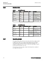
Monitored data
PID-3462-MONITOREDDATA v5
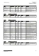
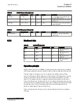
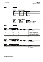
Table 91:
STBPTOC Monitored data
Name
Type
Values (Range)
Unit
Description
IL1
REAL
-
A
Current in phase L1
IL2
REAL
-
A
Current in phase L2
IL3
REAL
-
A
Current in phase L3
6.8.7
Operation principle
M12905-3 v5
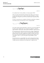
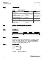
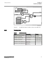
The sampled analog phase currents are pre-processed in a discrete Fourier filter
(DFT) block. From the fundamental frequency components of each phase current
the RMS value of each phase current is derived. These phase current values are fed
to a comparator in the stub protection function STBPTOC. In a comparator the
RMS values are compared to the set operating current value of the function
I>
.
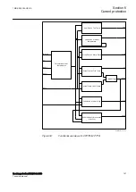
If a phase current is larger than the set operating current the signal from the
comparator for this phase is activated. This signal will, in combination with the
release signal from line disconnection (RELEASE input), activate the timer for the
TRIP signal. If the fault current remains during the timer delay
t
, the TRIP output
signal is activated. The function can be blocked by activation of the BLOCK input.
BLOCK
TRIP
STUB PROTECTION FUNCTION
STIL1
STIL2
STIL3
OR
AND
RELEASE
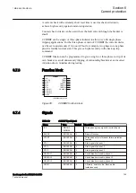
en05000731.vsd
IEC05000731 V1 EN-US
Figure 61:
Simplified logic diagram for Stub protection
1MRK 505 384-UEN A
Section 6
Current protection
Breaker protection REQ650 2.2 IEC
157
Technical manual
Summary of Contents for impreza 2017
Page 1: ...RELION 650 SERIES Breaker protection REQ650 Version 2 2 Technical manual...
Page 2: ......
Page 32: ...26...
Page 42: ...36...
Page 50: ...44...
Page 168: ...162...
Page 226: ...220...
Page 396: ...390...
Page 498: ...492...
Page 512: ...506...
Page 528: ...522...
Page 632: ...626...
Page 650: ...644...
Page 738: ...732...
Page 784: ...778...
Page 785: ...779...

