5.5.2
LED configuration alternatives
5.5.2.1
Functionality
GUID-1A03E0EF-C10F-4797-9D9F-5CCA86CA29EB v5
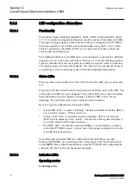
The function blocks LEDGEN and GRP1_LEDx, GRP2_LEDx and GRP3_LEDx
(x=1-15) controls and supplies information about the status of the indication LEDs.
The input and output signals of the function blocks are configured with PCM600.
The input signal for each LED is selected individually using SMT or ACT. Each
LED is controlled by the GRPn_LEDx (n=1-3) function block that controls the
color and the operating mode.
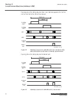
Each indication LED on local HMI can be set individually to operate in 6 different
sequences; two as follow type and four as latch type. Two of the latching sequence
types are intended to be used as a protection indication system, either in collecting
or restarting mode, with reset functionality. The other two are intended to be used
as signalling system in collecting mode with acknowledgment functionality.
5.5.2.2
Status LEDs
GUID-4822DF9C-E343-442B-B3F1-3FA8CD8DF234 v4
There are three status LEDs above the LCD in front of the IED: green, yellow and
red.
The green LED has a fixed function that presents the healthy status of the IED. The
yellow and red LEDs are user configured. The yellow LED can be used to indicate
that a disturbance report is triggered (steady) or that the IED is in test mode
(flashing). The red LED can be used to indicate a trip command.
Here is a typical configuration of the status LEDs:
•
Green LED: unlit > no power; blinking > startup or abnormal situation (IED is
not in service); steady > IED is in service
•
Yellow LED: unlit > no attention required; blinking > IED is in Testmode
(IED is not in normal service); steady > at least one of the signals configured
to turn the yellow LED on has been active
•
Red LED: unlit > no attention required; blinking > user performs a common
write from PCM600; steady > at least one of the signals configured to turn the
red LED on has been active
The yellow and red status LEDs are configured in the disturbance recorder
function, DRPRDRE, by connecting a start or trip signal from the actual function
to a BxRBDR binary input function block using the PCM600, and configuring the
setting to
Off
,
Start
or
Trip
for that particular signal.
5.5.2.3
Indication LEDs
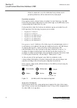
Operating modes
GUID-B67F1ED3-900B-4D34-8EEB-A3005999CE50 v4
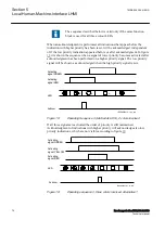
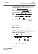
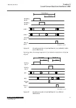
Collecting mode
Section 5
1MRK 505 384-UEN A
Local Human-Machine-Interface LHMI
70
Breaker protection REQ650 2.2 IEC
Technical manual
Summary of Contents for impreza 2017
Page 1: ...RELION 650 SERIES Breaker protection REQ650 Version 2 2 Technical manual...
Page 2: ......
Page 32: ...26...
Page 42: ...36...
Page 50: ...44...
Page 168: ...162...
Page 226: ...220...
Page 396: ...390...
Page 498: ...492...
Page 512: ...506...
Page 528: ...522...
Page 632: ...626...
Page 650: ...644...
Page 738: ...732...
Page 784: ...778...
Page 785: ...779...


