12.1.6
Monitored data
PID-6509-MONITOREDDATA v4
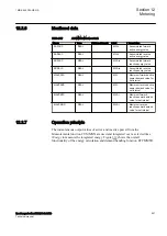
Table 373:
PCFCNT Monitored data
Name
Type
Values (Range)
Unit
Description
SCAL_VAL
REAL
-
-
Scaled value with time
and status information
12.1.7
Operation principle
IP14087-1 v2
M13397-3 v5
The registration of pulses is done for positive transitions (0-
>
1) on one of the 16
binary input channels located on the Binary Input Module (BIM). Pulse counter
values are sent to the station HMI with predefined cyclicity without reset.
The reporting time period can be set in the range from 1 second to 60 minutes and
is synchronized with absolute system time. Interrogation of additional pulse
counter values can be done with a command (intermediate reading) for a single
counter. All active counters can also be read by the LON General Interrogation
command (GI) or IEC 61850.
Pulse-counter logic (PCFCNT) function in the IED supports unidirectional
incremental counters. That means only positive values are possible. The counter
uses a 32 bit format, that is, the reported value is a 32-bit, signed integer with a
range 0...+2147483647. The counter is reset at initialization of the IED.
The reported value to station HMI over the station bus contains Identity, Scaled
Value (pulse count x scale), Time, and Pulse Counter Quality. The Pulse Counter
Quality consists of:
•
Invalid (board hardware error or configuration error)
•
Wrapped around
•
Blocked
•
Adjusted
The transmission of the counter value by SPA can be done as a service value, that
is, the value frozen in the last integration cycle is read by the station HMI from the
database. PCFCNT updates the value in the database when an integration cycle is
finished and activates the NEW_VAL signal in the function block. This signal can
be connected to an Event function block, be time tagged, and transmitted to the
station HMI. This time corresponds to the time when the value was frozen by the
function.
The pulse-counter logic function requires a binary input card,
BIMp, that is specially adapted to the pulse-counter logic function.
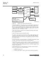
M13399-3 v9
Figure
shows the pulse-counter logic function block with connections of the
inputs and outputs.
1MRK 505 384-UEN A
Section 12
Metering
Breaker protection REQ650 2.2 IEC
495
Technical manual
Summary of Contents for impreza 2017
Page 1: ...RELION 650 SERIES Breaker protection REQ650 Version 2 2 Technical manual...
Page 2: ......
Page 32: ...26...
Page 42: ...36...
Page 50: ...44...
Page 168: ...162...
Page 226: ...220...
Page 396: ...390...
Page 498: ...492...
Page 512: ...506...
Page 528: ...522...
Page 632: ...626...
Page 650: ...644...
Page 738: ...732...
Page 784: ...778...
Page 785: ...779...


