background image

EI-44

EXTERIOR/INTERIOR TRIM

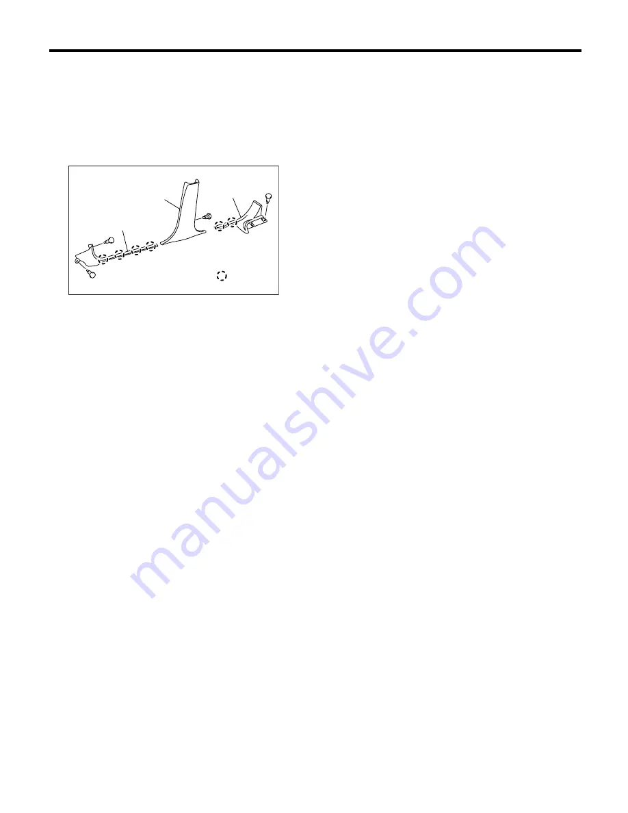
Lower Inner Trim

18.Lower Inner Trim

A: REMOVAL

1) Remove the side sill front cover (A).
2) Remove the rear seat cushion <Ref. to SE-13,
REMOVAL, Rear Seat.>, then remove
 side sill rear
cover (B).
3) Remove the center pillar lower trim (C).

B: INSTALLATION 

Install in the reverse order of removal.

CAUTION:
Be sure to securely hook pawls of inner trim 
panel to body flange.

(D) Clip

EI-00072

(A)

(C)

(B)

: (D)

Summary of Contents for 2004 Forester

Page 1: ... our customers by keeping their vehicle in optimum condition When replacement of parts during repair work is needed be sure to use SUBARU genuine parts All information illustration and specifi cations contained in this manual are based on the latest product information available at the time of publication approval HVAC SYSTEM HEATER VENTILATOR AND A C AC HVAC SYSTEM AUTO A C DIAGNOSTIC AC AIRBAG S...

Page 2: ...AL QUICK REFERENCE INDEX BODY SECTION G8080GE7 CRUISE CONTROL SYSTEM CC CRUISE CONTROL SYSTEM DIAGNOSTIC CC H4SO CRUISE CONTROL SYSTEM DIAGNOSTIC CC H4DOTC CRUISE CONTROL SYSTEM DIAGNOSTIC CC H4DOTC 2 5 IMMOBILIZER DIAGNOSTIC IM ...

Page 3: ...sembly 32 8 Blower Resistor Manual A C Model 33 9 Heater Core 34 10 Control Unit 35 11 Compressor 36 12 Condenser 37 13 Condenser Sub Fan 38 14 Heater Cooling Unit 39 15 Evaporator 40 16 Hose and Tube 41 17 Relay and Fuse 42 18 Pressure Switch Triple Pressure Switch 43 19 Ambient Sensor Auto A C Model 44 20 Sunload Sensor Auto A C Model 45 21 Air Vent Grille 46 22 Heater Duct 47 23 Heater Vent Duc...

Page 4: ...tor 260 W or less 12 5 V Fan type and size diameter width Sirocco fan type 150 75 mm 5 91 2 95 in Item Specifications Type of air conditioner Reheat air mix type Cooling capacity 5 1 kW 4 386 kcal h 17 403 BTU h Refrigerant HFC 134a CH2FCF3 0 6 0 05 kg 1 32 0 11 lb Compressor Type Vane rotary fix volume DKV 14G Discharge 140 cm3 8 54 cu in rev Max permissible speed 7 000 rpm Magnet clutch Type Dry...

Page 5: ...2 29 86 4 41 psi High pressure switch operating pressure ON OFF 2 940 200 kPa 29 98 2 03 kg cm2 426 32 28 87 psi OFF ON 590 200 kPa 6 02 2 03 kg cm2 85 6 28 87 psi Middle pressure switch operating pressure ON OFF 1370 120 kPa 13 97 1 22 kg cm2 198 65 17 35 psi OFF ON 1 770 100 kPa 18 05 1 02 kg cm2 256 81 14 50 psi Thermo control amplifier working temperature Evaporator outlet air Item Specificati...

Page 6: ...t 12 V Fan outer diameter 320 mm 12 6 in Radiator fan Main fan Motor type Magnet Power consumption 2 5 L turbo model and turbo AT model for EC and EK 120 W at 12 V Other model than above 70 W at 12 V Fan outer diameter 320 mm 12 6 in Idling speed A C ON MPFI model 800 100 rpm Triple switch Pressure switch Low pressure switch operating pressure ON OFF 177 25 kPa 1 80 0 25 kg cm2 25 60 3 56 psi OFF ...

Page 7: ... 3 Mode main lever 12 Mix actuator 21 Evaporator 4 Vent door lever 13 Mix door lever 22 Evaporator lining 5 Foot door lever 14 Foot door lever B 23 Evaporator sensor 6 Mode actuator link 15 Upper case 7 Defroster lever 16 Aspirator Tightening torque N m kgf m ft lb 8 Foot duct 17 Packing T 7 5 0 76 5 5 9 Lower case 18 Cooling unit pipe AC 00358 1 9 8 10 18 12 13 3 4 5 2 6 7 17 21 19 20 19 22 23 14...

Page 8: ...ctuator 21 Expansion valve 4 Vent door lever 13 Mix door lever 22 Evaporator 5 Foot door lever A 14 Foot door lever B 23 Evaporator lining 6 Mode actuator link 15 Upper case 24 Evaporator sensor 7 Defroster lever 16 Aspirator hose 8 Foot duct 17 Aspirator Tightening torque N m kgf m ft lb 9 Lower case 18 Packing T 7 5 0 76 5 5 AC 00001 1 9 8 10 11 16 19 12 13 3 4 5 2 6 7 18 22 20 21 20 23 24 14 15...

Page 9: ...e 18 Evaporator 3 Vent door lever 11 Mix actuator lever 19 Evaporator lining 4 Foot door lever 12 Foot door lever 20 Evaporator sensor 5 Mode actuator link 13 Upper case 6 Defroster lever 14 Packing Tightening torque N m kgf m ft lb 7 Foot duct 15 Cooling unit pipe T 7 5 0 76 5 5 8 Lower case 16 O ring AC 00359 1 8 7 9 15 11 2 3 4 5 6 14 18 16 17 16 19 20 12 13 T T T 10 ...

Page 10: ...ator lever 12 Mix actuator rod 21 Evaporator lining 4 Vent door lever 13 Mix actuator lever 22 Evaporator sensor 5 Foot door lever 14 Foot door lever 6 Mode actuator link 15 Upper case Tightening torque N m kgf m ft lb 7 Defroster lever 16 Packing T 7 5 0 76 5 5 8 Foot duct 17 Cooling unit pipe 9 Lower case 18 O ring AC 00084 1 9 8 10 11 17 12 13 3 4 5 2 6 7 16 20 18 19 18 21 22 14 15 T T T ...

Page 11: ...OR AND A C General Description 2 BLOWER MOTOR UNIT LHD MODEL WITH AUTO A C 1 Upper case 4 Link lever 7 Lower case 2 Air inlet select actuator 5 Filter cover 8 Blower motor ASSY 3 Air inlet select link 6 Cover AC 00334 1 5 3 2 4 6 7 8 ...

Page 12: ...ER VENTILATOR AND A C General Description RHD MODEL WITH AUTO A C 1 Upper case 4 Link lever 7 Lower case 2 Air inlet select actuator 5 Filter cover 8 Blower motor ASSY 3 Air inlet select link 6 Cover AC 00332 1 5 3 2 4 6 7 8 ...

Page 13: ...TOR AND A C General Description LHD MODEL WITH MANUAL A C 1 Upper case 4 Link rod 7 Cover 2 Air inlet select actuator 5 Filter cover 8 Lower case 3 Air inlet select link 6 Blower resistor 9 Blower motor ASSY AC 00209 1 5 3 2 4 7 8 6 9 ...

Page 14: ... A C General Description RHD MODEL WITH MANUAL A C 1 Upper case 4 Air inlet select link 7 Cover 2 Air inlet select actuator 5 Filter cover 8 Lower case 3 Air inlet select lever 6 Blower resister 9 Blower motor ASSY AC 00085 1 5 3 2 4 7 8 6 9 ...

Page 15: ...C SYSTEM HEATER VENTILATOR AND A C General Description 3 CONTROL UNIT AUTO A C MODEL 1 Panel 4 Control case front 7 Control case rear 2 Control dial 5 Bulb 3 Switch 6 Control unit circuit AC 00210 7 6 5 4 1 2 3 ...

Page 16: ...HD MODEL WITH MANUAL A C 1 Panel 5 A C switch 9 Mode control cable 2 Temperature control dial 6 Air inlet select switch 10 Temperature control cable 3 Fan dial 7 Rear defogger switch 11 Bulb 4 Mode control dial 8 Switch circuit board AC 00211 2 6 5 7 4 3 1 8 10 9 11 ...

Page 17: ...HD MODEL WITH MANUAL A C 1 Panel 5 A C switch 9 Mode control cable 2 Mode control dial 6 Rear defogger switch 10 Temperature control cable 3 Fan dial 7 Air inlet select switch 11 Bulb 4 Temperature control dial 8 Switch circuit board AC 00333 2 6 5 7 4 3 1 8 10 9 11 ...

Page 18: ...ription 4 AIR CONDITIONING UNIT LHD MODEL 1 Condenser 5 Compressor Tightening torque N m kgf m ft lb 2 High pressure hose 6 O ring T1 7 4 0 75 5 4 3 Low pressure hose 7 Triple pressure switch T2 15 1 5 10 8 4 Pipe AC 00866 1 3 4 7 5 2 T1 T1 T2 6 6 6 6 6 T2 6 ...

Page 19: ... General Description RHD MODEL 1 Condenser 5 Compressor Tightening torque N m kgf m ft lb 2 High pressure hose 6 O ring T1 7 4 0 75 5 4 3 Low pressure hose 7 Triple pressure switch T2 15 1 5 10 8 4 Pipe AC 00243 1 3 4 7 5 2 T1 T1 T2 6 6 6 6 6 T2 ...

Page 20: ...Compressor belt cover Non turbo model Tightening torque N m kgf m ft lb 2 Idler pulley adjuster T1 4 0 0 40 2 95 3 Idler pulley 8 Compressor stay T2 22 6 2 3 16 6 4 Compressor bracket T3 23 0 2 35 17 0 5 Compressor T4 28 9 2 95 21 3 6 V belt T5 35 3 6 26 AC 00335 1 3 2 4 5 8 6 7 T3 T2 T1 T5 T5 T5 T4 T4 ...

Page 21: ...ER VENTILATOR AND A C General Description 6 HEATER DUCT 1 Front defroster nozzle 3 Side defroster duct RH 5 Side ventilation duct RH 2 Side defroster duct LH 4 Side ventilation duct LH 6 Rear heater duct AC 00212 1 3 5 6 2 4 ...

Page 22: ...FC 12 refrigerant cannot be used in the HFC 134a A C system The HFC 134a refrigerant also cannot be used in the HFC 12 A C system If an incorrect or no refrigerant is used poor lu brication will result and the compressor itself may be damaged 4 HANDLING OF REFRIGERANT The refrigerant boils at approx 30 C 22 F When handling it be sure to wear safety goggles and protective gloves Direct contact of t...

Page 23: ...f the O rings be fore installation Apply compressor oil to the bead of tube After tightening use a clean cloth to remove ex cess compressor oil from the connections and any oil which may have run on the vehicle body or other parts If any leakage is suspected after tightening do not retighten the connections disconnect the con nections remove the O rings and check the O rings threads and connection...

Page 24: ...and hose fittings Applicator bottle A small APPLICATOR BOTTLE is recommended to apply refrigerant oil to the various parts They can be available at a hardware or drug store Manifold gauge set A MANIFOLD GAUGE SET with hoses can be available at from either a refrigerant supplier or an automotive equipment supplier Refrigerant recovery system A REFRIGERANT RECOVERY SYSTEM is used for the recovery an...

Page 25: ...mp A VACUUM PUMP in good working condition is necessary and can be available at either a refrigerant supplier or an automotive equipment supplier Can tap A CAN TAP for the 397 g 14 oz can is available at an automotive equipment supplier Thermometer Pocket THERMOMETERS are available at either a industrial hardware store or a refrigerant suppliers Illustration Tools and Equipment AC 00015 AC 00016 A...

Page 26: ...TECTOR can be available at either a spe cialty tool supplier or an A C equipment supplier Weight scale A WEIGHT SCALE such as an electronic charging scale or a bath room scale with digital display will be needed if a 13 6 kg 30 lb refrig erant container is used Illustration Tools and Equipment AC 00019 AC 00020 ...

Page 27: ...efective condenser fan motor Clogged condenser fin Too much refrigerant Air inside the system Defective receiver dryer Replace the fan motor Clean the condenser fin Discharge refrigerant Replace the receiver dryer After reevacuating the receiver dryer charge appropriate amount of refriger ant High pressure side is unusually low Defective compressor Not enough refrigerant Clogged expansion valve Ex...

Page 28: ...ration manual attached to the refrigerant recovery system 1 Perform the compressor oil return operation Ref to AC 31 OPERATION Compressor Oil 2 Stop the engine 3 Make sure the valves on low high pressure sides of manifold gauge set are fully closed 4 Install the low high pressure hoses to the ser vice ports on the low high pressure sides of the vehicle respectively 5 Connect the center hose to the...

Page 29: ...auge 2 Install the low high pressure hoses to corre sponding service ports on vehicle CAUTION Be sure that the hoses are securely connected 3 Connect the center hose of manifold gauge with vacuum pump 4 Activate the vacuum pump and then open the valves on low high pressure sides CAUTION Be sure to evacuate the system using vacuum pump 5 After at least 5 minutes of evacuation if the low pressure ga...

Page 30: ...o allow the air in the center hose to escape by the refriger ant 14 Make sure that the high pressure valve of man ifold gauge is closed and then open the low pres sure side valve only to charge the refrigerant CAUTION Do not open the high pressure valve Be sure to open the low pressure valve 15 Close the low pressure valve when the low pressure gauge reading reaches 200 kPa 1 500 mmHg 59 1 inHg 16...

Page 31: ...N Engine running at 1 500 rpm Blower speed setting to HI Temperature setting to MAX COOL Air inlet setting to RECIRC Window open 23 Open the low pressure valve and charge the specified amount of refrigerant 24 Close all valves and disconnect the hoses from service port after charging the refrigerant 25 Install the cap to service port ...

Page 32: ...nt of leakage about 28 g 1 0 oz per year This is not a problem 8 Starting from the connection between the low pressure pipe and evaporator check the system for leakage along the low pressure side through the compressor The following items must be checked thoroughly Connection between two parts Connection between the pipe and plate 9 Visually check the rubber area of the flexible hose for cracks Ch...

Page 33: ...this condition for 10 minutes B REPLACEMENT NOTE If a component is replaced add an appropriate amount of compressor oil same as the amount of remaining oil in removed component When replacing the compressor the new com pressor will already have the specified amount of oil in it Install the new compressor after removing the same amount of oil that is remaining in the com pressor removed Replacement...

Page 34: ... to remove blower motor unit assembly B INSTALLATION Install in the reverse order of removal Tightening torque Refer to COMPONENT in General Descrip tion Ref to AC 5 HEATER COOLING UNIT COMPONENT General Description Ref to AC 9 BLOWER MOTOR UNIT COMPONENT General Description C INSPECTION Inspection of Auto A C Brush less Motor Operation Connect the motor connector terminal 1 from the battery to th...

Page 35: ... Disconnect the blower resistor connector 3 Remove the two screws to remove blower resis tor B INSTALLATION Install in the reverse order of removal C INSPECTION Measure the blower resistor resistance If NG replace the blower resistor Terminal No Standard 3 and 6 Approx 0 4 Ω 3 and 4 Approx 1 1 Ω 2 and 1 Approx 2 6 Ω AC 00221 AC 00245 MO H MH ML L 2 3 6 4 1 0 4 0 7 1 5 1 2 3 4 6 ...

Page 36: ... the screws to remove the heater core pipe cover RHD model 3 Remove the screws to remove mode actuator 4 Remove the screws to remove foot duct 5 Remove the screws to remove evaporator cover 6 Remove the screws to remove lower case 7 Remove the heater core B INSTALLATION Install in the reverse order of removal AC 00042 AC 00043 AC 00044 AC 00867 AC 00046 AC 00047 ...

Page 37: ...r console panel and instru ment panel pad 5 Loosen the screws 6 Insert the flat tip screwdriver to the position A and release the claw with pulling out the lower por tion of center console panel CAUTION Do not insert the flat tip screwdriver into any portion except for indicated in the figure The in strument panel may be damaged 7 Remove the four screws on rear side of center console panel and the...

Page 38: ...ound cable from battery 5 Remove the V belt Ref to ME H4SO 43 RE MOVAL V belt Ref to ME H4DOTC 52 RE MOVAL V belt 6 Remove the generator Ref to SC H4SO 15 REMOVAL Generator 7 Remove the low pressure hose and high pres sure hose 8 Disconnect the compressor harness from body harness 9 Remove the bolts to remove compressor brack et 10 Remove the bolts and then separate compres sor and bracket C INSTA...

Page 39: ...essor oil to the compressor Ref to AC 31 REPLACEMENT Compressor Oil B INSTALLATION 1 Install in the reverse order of removal CAUTION Replace the O rings on hoses or pipes with new ones and then apply compressor oil Confirm that lower guide of condenser has been fitted into holes on radiator panel 2 Charge refrigerant Ref to AC 27 OPERA TION Refrigerant Charging Procedure Tightening torque Refer to...

Page 40: ...STEM HEATER VENTILATOR AND A C Condenser Sub Fan 13 Condenser Sub Fan A REMOVAL Ref to CO H4SO 35 REMOVAL Radiator Main Fan and Fan Motor B INSTALLATION Ref to CO H4SO 37 INSTALLATION Radiator Main Fan and Fan Motor ...

Page 41: ...ngine compartment to remove the hoses 5 Remove the instrument panel Ref to EI 40 REMOVAL Instrument Panel Assembly 6 Remove the support beam 7 Remove the blower motor unit assembly Ref to AC 32 REMOVAL Blower Motor Unit Assem bly 8 Disconnect the servo motor connectors 9 Remove the bolt and nuts to remove the heater and cooling unit B INSTALLATION 1 Install in the reverse order of removal 2 Charge...

Page 42: ...ove evaporator cov er 5 Remove the A C pipes in unit 6 Rotate the upper part of evaporator tilt toward the front vehicle and the lower part tilt toward the in terior respectively Then pull out the heater case to the left side 7 Remove the two bolts to remove expansion valve CAUTION If the evaporator is replaced add appropriate amount of compressor oil to evaporator Ref to AC 31 REPLACEMENT Compres...

Page 43: ...bolts C 9 Disconnect the high pressure hose from com pressor 10 Disconnect the high pressure hose from con denser 11 Remove the high pressure hose from vehicle 12 Remove the high pressure tube attaching bolt D 13 Remove the high pressure tube from vehicle B INSTALLATION CAUTION When disconnecting connecting hoses do not apply an excessive force to them Confirm that no torsion and excessive tension...

Page 44: ...rmi nals 1 and 2 check continuity between the ter minals 3 and 5 If no continuity exists replace the relay with a new one 1 Main fuse box M B 2 Main fan relay 3 Sub fan relay 4 A C relay 5 Fan mode relay 6 Main fan fuse 7 Sub fan fuse AC 00834 7 6 5 4 1 3 2 1 2 Continuity exists 3 4 Continuity exists 3 5 No continuity AC 00093 4 4 5 2 2 5 3 3 1 1 ...

Page 45: ...e ON OFF opera tion of the pressure switch AC 00248 3 1 4 2 Terminal No Operation Standard kPa kg cm2 psi High and low pressure switch 1 and 2 Turns OFF Pressure increases up to 2 940 200 30 0 2 427 28 Pressure decreases down to 177 25 1 8 0 3 26 4 Turns ON Pressure increases up to 206 30 2 1 0 3 30 4 Pressure decreases down to 2 350 200 24 2 341 28 Middle pressure switch 3 and 4 Turns OFF Pressur...

Page 46: ...A REMOVAL 1 Open the front hood 2 Disconnect the ground cable from battery 3 Disconnect the ambient sensor connector 4 Remove the ambient sensor from radiator lower panel B INSTALLATION Install in the reverse order of removal C INSPECTION Ref to AC 32 AMBIENT SENSOR Diagnostic Procedure for Sensors AC 00125 ...

Page 47: ...MOVAL 1 Disconnect the ground cable from battery 2 Disconnect the sunload sensor connector CAUTION Be careful not to damage the sensors and inte rior trims when removing them B INSTALLATION Install in the reverse order of removal C INSPECTION Ref to AC 39 SUNLOAD SENSOR Diagnostic Procedure for Sensors AC 00126 ...

Page 48: ...Ref to EI 40 REMOVAL Instrument Panel Assembly 3 Loosen the two screws to remove the center air vent grille 2 SIDE GRILLE Remove the side vent grille by prying four points B INSTALLATION Install in the reverse order of removal C INSPECTION 1 Check that the direction and amount of air can be adjusted smoothly 2 Check that the adjustment can be kept in each position AC 00060 AC 00249 ...

Page 49: ...r Duct 22 Heater Duct A REMOVAL 1 Remove the front seat Ref to SE 6 REMOV AL Front Seat 2 Remove the front side sill cover 3 Pull off the floor mat remove the cover and then remove the heater duct B INSTALLATION Install in the reverse order of removal ...

Page 50: ...A C Heater Vent Duct 23 Heater Vent Duct A REMOVAL 1 Remove the instrument panel Ref to EI 40 REMOVAL Instrument Panel Assembly 2 Remove the screws 3 Remove the heater vent duct B INSTALLATION Install in the reverse order of removal AC 00224 ...

Page 51: ...lts to remove the heater cock solenoid from the bracket 6 Pull out the heater cock solenoid Loosen the hose clamp and disconnect the two heater hoses B INSTALLATION Install in the reverse order of removal C INSPECTION 1 Remove the heater cock solenoid valve Ref to AC 49 REMOVAL Heater Cock Solenoid Valve 2 Connect the positive terminal of battery to No 1 terminal of heater cock solenoid valve and ...

Page 52: ...h Noise V Belt Magnet clutch Compressor Condenser fan Does not run Fuse Sub fan relay Wiring harness Noise Condenser fan motor Cold air not emitted Refrigerant V Belt Magnet clutch Compressor Pressure switch Blower fan relay Blower motor A C switch Blower switch Wiring harness Heater duct Heater vent duct Control unit Expansion valve Evaporator Air mix actuator Auto A C Temperature control cable M...

Page 53: ...arness Air mix actuator Auto A C Temperature control cable Manual A C Temperature adjustment switch Unable to switch blow vents Wiring harness Mode actuator Auto A C Mode control cable Manual A C Mode switch Unable to switch suction vents Wiring harness FRESH RECIRC actuator Air inlet select switch Symptom Repair order ...

Page 54: ...AC 52 HVAC SYSTEM HEATER VENTILATOR AND A C General Diagnostics ...

Page 55: ...al Description 3 3 Electrical Component Location 5 4 Auto A C Control Module I O Signal 7 5 Diagnostic Chart for Self Diagnosis 9 6 Diagnostics for A C System Malfunction 12 7 Diagnostic Procedure for Actuators 21 8 Diagnostic Procedure for Sensors 32 9 General Diagnostic Table 41 ...

Page 56: ...unction part be identified Repair the mal function part in accordance with each diagnostic chart Go to step 3 3 CHECK COMPARTMENT TEMPERATURE 1 Turn ON the A C switch 2 Turn the temperature control dial at maxi mum cool position 3 Check the compartment temperature change Does the compartment tem perature change Go to step 4 Ref to AC 16 COMPARTMENT TEMPERATURE DOES NOT CHANGE OR A C SYSTEM DOES NO...

Page 57: ...s which might affect A C system problems 1 BATTERY 1 Measure battery voltage and specific gravity of electrolyte Standard voltage 12 V Specific gravity More than 1 260 2 Check the condition of the fuses for A C system power supply and other fuses 3 Check the condition of harness and harness connector connections 2 ASPIRATOR HOSE 1 Turn the ignition switch to ON and press the A C switch 2 Turn the ...

Page 58: ...TO Outlet opening AUTO Inlet opening AUTO Compressor AUTO 4 Turn the temperature control dial to the right fully and set maximum hot position Outlet air temperature HOT Fan speed 4th Outlet opening HEAT Inlet opening FRESH Compressor AUTO 3 Defroster switch Press the defroster switch Outlet air temperature AUTO Fan speed AUTO Outlet opening DEF Inlet opening FRESH Compressor ON 4 FRESH RECIRC swit...

Page 59: ...C SYSTEM AUTO A C DIAGNOSTIC Electrical Component Location 3 Electrical Component Location A LOCATION 1 ENGINE COMPARTMENT 1 A C compressor 3 Pressure switch 4 Ambient sensor 2 A C relay AC 00097 1 2 4 1 3 2 3 ...

Page 60: ...STIC Electrical Component Location 2 PASSENGER COMPARTMENT 1 Mode door actuator 4 Intake door actuator 7 Air mix door actuator 2 In vehicle sensor 5 Blower motor 3 Sunload sensor 6 Evaporator sensor AC 00098 1 6 4 5 7 7 6 5 4 3 1 2 3 ...

Page 61: ... inlet FRESH other positions 12 V 0 V B19 Air inlet MIX other positions 12 V 0 V B18 Air inlet RECIRC other positions 12 V 0 V B17 A C ON signal A C ON A C OFF 0 V 8 10 V B16 Blower motor control 3 3 B15 Blower fan ON signal When blower fan running when blower fan not running 12 V 0 V B13 Engine coolant temperature sensor When the engine coolant is at 49 C 120 F 8 9 V B12 In vehicle sensor B11 Gro...

Page 62: ...gnal B WIRING DIAGRAM Ref to WI 58 WIRING DIAGRAM Air Conditioning System A14 Combination meter ambient temperature sig nal 3 3 A13 Mode door actuator position detection signal Outlet VENT BI LEVEL HEAT 5 V DEF HEAT DEF 0 V A12 Mode door actuator position detection signal Outlet VENT DEF HEAT 5 V BI LEVEL HEAT DEF 0 V A10 A C cutout signal A C ON Battery voltage Pressure switch operated 0 V A9 Ill...

Page 63: ...itch 9 Fan speed control dial 1 Normal Operation 6 After the LED display Approx 20 sec 9 Output Equipment Operation Sequential Operation 2 Switch 3 IG OFF ON with pressing 7 Sensor Check Sequential Opera tion 10 Output Equipment Operation Phased Operation 4 Self Diagnosis Mode 5 LED Display Check 8 Sensor Check Phased Operation AC 00250 5 6 7 8 9 4 3 2 1 AC 00242 OFF AUTO AUTO AUTO AUTO AUTO 5 4 3...

Page 64: ...off NOTE Rear window defogger LED illuminates in case of stored malfunction but does not illuminate in case of present malfunction Does each DEF MODE and fan speed LED turn off Go to step 4 Confirm the com bination of illumi nating LEDs by using Sensor Check Table and identify the mal functioning sensor before repairing Ref to AC 11 SENSOR CHECK TABLE OPERA TION Diagnostic Chart for Self Diagnosis...

Page 65: ...ff Illuminate 2 Ambient sensor BI LEVEL LED blinks BI LEVEL LED blinks 3 Evaporator sensor HEAT LED blinks HEAT LED blinks 4 Sunload sensor 1 DEF HEAT LED blinks DEF HEAT LED blinks 5 Air mix door actuator P B R Fan speed 1st LED blinks Fan speed 1st LED blinks 6 Combination meter commu nication Ambient sensor Fan speed 2nd LED blinks Fan speed 2nd LED blinks When all parts are in good condition T...

Page 66: ...ot operate WIRING DIAGRAM AC 00149 A i48 B i49 B201 1 2 3 4 5 6 7 8 9 10 11 12 13 14 15 16 1 2 3 4 5 6 7 8 9 10 11 12 13 14 15 16 17 18 19 20 E A i48 B i49 i40 B201 SBF 1 BATTERY IGNITION SWITCH AUTO A C CONTROL MODULE M B NO 2 SBF 4 F B NO 17 B5 B4 B11 3 4 1 2 8 9 10 11 12 13 14 15 16 17 18 19 20 21 22 23 24 5 6 7 B202 3 4 1 2 8 9 10 11 12 13 14 15 16 17 18 19 20 21 22 23 24 5 6 7 LHD 14 4 10 19 ...

Page 67: ... ground Is the voltage more than 10 V Go to step 4 Check open or short circuit in har ness between auto A C control mod ule and fuse 4 CHECK AUTO A C CONTROL MODULE POWER CIRCUIT Measure the voltage between auto A C control module connector terminal and chassis ground after turning the ignition switch to ON position Connector terminal i49 No 5 Chassis ground Is the voltage more than 10 V Go to ste...

Page 68: ...SBF 3 F B NO 1 SBF 4 F B NO 2 F B NO 17 B16 B15 18 B202 B202 i41 22 3 4 1 2 1 2 3 4 5 6 1 2 3 4 5 6 7 8 9 10 11 12 13 14 15 16 1 2 3 4 5 6 7 8 9 10 11 12 13 14 15 16 17 18 19 20 3 4 1 2 8 9 10 11 12 13 14 15 16 17 18 19 20 21 22 23 24 5 6 7 A i48 B i49 BATTERY IGNITION SWITCH BLOWER MOTOR RELAY BLOWER MOTOR B201 3 4 1 2 8 9 10 11 12 13 14 15 16 17 18 19 20 21 22 23 24 5 6 7 3 RHD RHD LHD LHD LHD M...

Page 69: ...TOR RELAY 1 Turn the ignition switch to OFF 2 Remove the blower motor relay 3 Connect the battery positive terminal to terminal No 1 of blower motor relay and nega tive terminal to terminal No 3 4 Measure the resistance between terminals No 2 and 4 Terminals No 2 No 4 Is the resistance less than 1 Ω Go to step 4 Replace the blower motor relay 4 CHECK BLOWER MOTOR 1 Disconnect the connector from bl...

Page 70: ... 8 9 10 11 17 19 20 12 13 14 1 2 3 4 5 6 7 8 9 10 11 12 13 14 15 16 17 18 19 20 21 22 23 24 25 26 27 28 29 30 31 32 33 34 35 AUTO A C CONTROL MODULE ECM 24 21 1 2 3 4 5 6 7 8 9 10 11 12 13 14 15 16 17 18 19 20 1 2 3 4 5 6 7 8 9 10 11 12 13 14 15 16 5 6 7 8 2 1 9 4 3 10 24 22 23 25 11 12 13 14 15 26 16 17 18 19 20 21 3 4 1 2 8 9 10 11 12 13 14 15 16 17 18 19 20 21 22 23 24 5 6 7 D B137 B B135 C B13...

Page 71: ...5 AUTO A C CONTROL MODULE ECM 21 23 5 6 7 8 2 1 9 4 3 10 24 22 23 25 11 12 13 14 15 26 16 17 18 19 20 21 3 4 1 2 8 9 10 11 12 13 14 15 16 17 18 19 20 21 22 23 24 5 6 7 D B137 B B135 C B136 A i48 1 2 3 4 5 6 7 8 9 10 11 12 13 14 15 16 B i49 1 2 3 4 5 6 7 8 9 10 11 12 13 14 15 16 17 18 19 20 TURBO MODEL B33 NON TURBO MODEL A9 1 TURBO MODEL B24 NON TURBO MODEL A13 2 TURBO MODEL B25 NON TURBO MODEL A1...

Page 72: ...ECK THE A C CUT SIGNAL CIRCUIT 1 Disconnect the connector from auto A C control module 2 Measure the resistance between auto A C control module and pressure switch connector Connector terminal i48 No 10 F79 No 2 Is the resistance less than 1 Ω Go to step 6 Repair the har ness between auto A C control mod ule and pressure switch 6 CHECK THE A C ON SIGNAL CIRCUIT 1 Disconnect the connector from ECM ...

Page 73: ...ess for main fan motor power sup ply circuit 11 CHECK GROUND CIRCUIT OF MAIN FAN MOTOR Measure the resistance between main fan motor harness connector and chassis ground Connector terminal Except turbo AT model F17 No 1 Chassis ground Turbo AT model F17 No 2 Chassis ground Is the resistance less than 1 Ω Go to step 12 Repair the har ness for main fan motor ground cir cuit 12 CHECK MAIN FAN MOTOR C...

Page 74: ...stance between sub fan motor harness connector and chassis ground Connector terminal Except turbo AT model F16 No 1 Chassis ground Turbo AT model F16 No 2 Chassis ground Is the resistance less than 1 Ω Go to step 17 Repair the har ness for sub fan motor ground cir cuit 17 CHECK SUB FAN MOTOR Connect the battery positive terminal to ter minal No 2 and ground terminal to termi nal No 1 of sub fan mo...

Page 75: ...6 1 2 3 4 5 6 7 8 9 10 11 12 13 14 15 16 17 18 19 20 B91 i41 B202 IGNITION SWITCH BATTERY SBF 1 SBF 4 F B NO 17 4 3 14 13 12 B18 B20 B19 1 2 3 4 B202 3 4 1 2 8 9 10 11 12 13 14 15 16 17 18 19 20 21 22 23 24 5 6 7 A i48 B i49 AUTO A C CONTROL MODULE INTAKE DOOR ACTUATOR B201 3 4 1 2 8 9 10 11 12 13 14 15 16 17 18 19 20 21 22 23 24 5 6 7 LHD MODEL RHD MODEL LHD RHD LHD MODEL 2 RHD MODEL 1 LHD MODEL ...

Page 76: ...del i49 No 18 B91 No 2 i49 No 19 B91 No 3 i49 No 20 B91 No 1 RHD model i49 No 18 B91 No 1 i49 No 19 B91 No 3 i49 No 20 B91 No 2 Is the resistance less than 1 Ω Go to step 3 Repair the har ness between auto A C control mod ule and intake door actuator 3 CHECK OPERATION OF INTAKE DOOR AC TUATOR 1 Connect the intake door actuator connec tor 2 Ground the auto A C control module con nector with a suita...

Page 77: ...77 A i48 B i49 B202 1 2 3 4 5 6 7 8 9 10 11 12 13 14 15 16 1 2 3 4 5 6 7 8 9 10 11 12 13 14 15 16 17 18 19 20 3 4 1 2 8 9 10 11 12 13 14 15 16 17 18 19 20 21 22 23 24 5 6 7 B77 i41 B202 4 7 1 2 10 8 9 5 6 11 10 8 6 7 9 15 B8 B9 A5 A4 A12 A13 A16 1 2 3 4 5 6 7 8 9 10 A i48 B i49 AUTO A C CONTROL MODULE MODE ACTUATOR LHD MODEL RHD MODEL LHD RHD 17 18 5 4 7 8 9 LHD RHD ...

Page 78: ...tch 2 Turn the mode control dial to VENT position and measure the voltage between auto A C control module and chassis ground when DEF is changed to VENT position Connector terminal i49 No 8 Chassis ground Is the voltage more than 12 V Go to step 4 Replace the auto A C control mod ule 4 CHECK POWER SUPPLY FOR ACTUATOR SIDE 1 Press the defroster switch 2 Turn the mode control dial to VENT position a...

Page 79: ...OFF 2 Disconnect the connectors from auto A C control module and mode door actuator 3 Measure the resistance of harness between auto A C control module and mode door actuator Connector terminal i48 No 4 B77 No 5 Is the resistance less than 1 Ω Replace the auto A C control mod ule Repair the har ness between auto A C control mod ule and mode door actuator 9 CHECK AUTO A C CONTROL MODULE SIG NAL VOL...

Page 80: ... SUPPLY 1 Turn the ignition switch to OFF 2 Disconnect the connector from mode door actuator 3 Turn the ignition switch to ON 4 Measure the voltage between mode door actuator harness connector and chassis ground Connector terminal B77 No 4 7 Chassis ground Is the voltage 5 V Go to step 15 Go to step 14 14 CHECK HARNESS BETWEEN AUTO A C CONTROL MODULE AND MODE DOOR AC TUATOR 1 Turn the ignition swi...

Page 81: ...ween auto A C control module and mode door actuator Connector terminal i48 No 13 B77 No 8 Is the resistance less than 1 Ω Replace the auto A C control mod ule Repair the har ness between auto A C control mod ule and mode door actuator 18 CHECK ACTUATOR GROUND CIRCUIT 1 Turn the ignition switch to OFF 2 Disconnect the connector from auto A C control module 3 Measure the resistance of harness betwee...

Page 82: ...R TROUBLE SYMPTOM Outlet air temperature does not change WIRING DIAGRAM LHD model AC 00106 i65 A i48 B i49 1 2 3 4 5 6 7 8 9 10 11 12 13 14 15 16 1 2 3 4 5 6 7 8 9 10 11 12 13 14 15 16 17 18 19 20 i65 4 3 1 2 6 A7 A16 B1 B7 B6 1 2 3 4 5 6 A i48 B i49 AUTO A C CONTROL MODULE AIR MIX DOOR ACTUATOR ...

Page 83: ...B i49 1 2 3 4 5 6 7 8 9 10 11 12 13 14 15 16 1 2 3 4 5 6 7 8 9 10 11 12 13 14 15 16 17 18 19 20 B293 4 3 1 2 6 A7 A16 B1 B7 B6 1 2 3 4 5 6 A i48 B i49 AUTO A C CONTROL MODULE AIR MIX DOOR ACTUATOR AC 00155 6 9 10 16 15 i41 B202 B202 3 4 1 2 8 9 10 11 12 13 14 15 16 17 18 19 20 21 22 23 24 5 6 7 ...

Page 84: ...lace the auto A C control mod ule 3 CHECK POWER SUPPLY FOR AIR MIX DOOR ACTUATOR Measure the voltage between auto A C control module connector and chassis ground after turning the temperature control dial to maxi mum HOT position Connector terminal i49 No 7 Chassis ground Is the voltage 7 V at normal temperature Go to step 4 Replace the auto A C control mod ule 4 CHECK HARNESS BETWEEN AUTO A C CON...

Page 85: ...age between auto A C con trol module connector terminals while chang ing the setting temperature between maximum COOL and maximum HOT Connector terminal i49 No 1 i48 No 16 Does the voltage change between 0 5 Max HOT 4 5 Max COOL V Go to step 6 Replace the air mix door actuator 6 CHECK POOR CONTACT Check poor contact in auto A C control module and connector Is there poor contact in con nector Repai...

Page 86: ... i10 1 2 3 4 5 6 7 8 9 10 11 12 13 14 15 16 1 2 3 4 5 6 7 8 9 10 11 12 13 14 15 16 17 18 19 20 3 4 1 2 8 9 10 11 12 13 14 15 16 17 18 19 20 21 22 23 24 5 6 7 i41 B202 B202 B38 i3 B38 B i10 COMBINATION METER A i48 B i49 19 A14 24 B30 1 2 3 4 5 6 7 8 9 10 11 12 13 14 15 16 17 18 19 20 21 22 23 24 25 26 27 28 29 30 21 9 32 1 2 3 4 5 6 10 11 12 13 14 15 7 16 23 30 19 20 22 26 27 28 29 8 17 24 31 18 25...

Page 87: ... 15 16 17 18 19 20 21 22 23 24 5 6 7 i41 B202 B202 B i10 COMBINATION METER A i48 B i49 3 A14 B30 1 2 3 4 5 6 7 8 9 10 11 12 13 14 15 16 17 18 19 20 21 22 23 24 25 26 27 28 29 30 AUTO A C CONTROL MODULE i2 B37 14 15 2 1 B24 B25 18 17 B100 F2 F78 AMBIENT SENSOR F2 1 2 F78 21 14 13 16 MT MODEL AT MODEL 3 4 1 2 8 9 10 11 12 13 14 15 16 17 18 19 20 21 22 5 6 7 3 4 1 2 8 9 10 11 12 13 14 15 16 17 18 5 6...

Page 88: ... meter Connector terminal i10 No 30 i48 No 14 Is the resistance less than 1 Ω Go to step 2 Repair the har ness between auto A C control mod ule and combina tion meter 2 CHECK AMBIENT SENSOR CIRCUIT Check the ambient sensor circuit Ref to IDI 8 CHECK OUTSIDE TEMPERATURE INDI CATOR INSPECTION Combination Meter System Is the ambient sensor circuit normal Go to step 3 Repair the ambi ent sensor circui...

Page 89: ...ambient sensor is indicated in self diagnosis WIRING DIAGRAM AC 00157 A i48 B i49 1 2 3 4 5 6 7 8 9 10 11 12 13 14 15 16 1 2 3 4 5 6 7 8 9 10 11 12 13 14 15 16 17 18 19 20 i55 IN VEHICLE SENSOR A i48 B i49 A16 1 B12 2 1 2 AUTO A C CONTROL MODULE LHD LHD RHD RHD LHD RHD LHD RHD 9 24 B314 LHD MODEL RHD MODEL LHD RHD LHD RHD LHD RHD i55 B314 LHD RHD 3 4 1 2 8 9 10 11 12 13 14 15 16 17 18 19 20 21 22 ...

Page 90: ...connector terminals of auto A C control module Connector terminal i49 No 12 i48 No 16 Is the voltage approx 5 V Go to step 4 Go to step 6 4 CHECK HARNESS BETWEEN AUTO A C CONTROL MODULE AND IN VEHICLE SEN SOR 1 Turn the ignition switch to OFF 2 Disconnect the connector from auto A C control module 3 Measure the resistance in harness between auto A C control module and in vehi cle sensor Connector ...

Page 91: ...00158 A i48 B i49 B256 1 2 3 4 5 6 7 8 9 10 11 12 13 14 15 16 1 2 3 4 5 6 7 8 9 10 11 12 13 14 15 16 17 18 19 20 3 4 1 2 8 9 10 11 12 13 14 15 16 17 18 19 20 21 22 23 24 5 6 7 B202 B202 i41 B256 A i48 B i49 A16 5 1 B2 3 15 1 2 3 EVAPORATOR SENSOR AUTO A C CONTROL MODULE 11 9 RHD LHD LHD MODEL RHD MODEL LHD RHD ...

Page 92: ...o A C control module Connector terminal i49 No 2 i48 No 16 Is the voltage approx 5 V Go to step 4 Go to step 6 4 CHECK HARNESS CONNECTOR BETWEEN AUTO A C CONTROL MODULE AND EVAP ORATOR SENSOR 1 Turn the ignition switch to OFF 2 Disconnect the connector from auto A C control module 3 Measure the resistance in harness between auto A C control module and evapo rator sensor Connector terminal B256 No ...

Page 93: ...nes directly on it WIRING DIAGRAM AC 00885 A i48 B i49 1 2 3 4 5 6 7 8 9 10 11 12 13 14 15 16 1 2 3 4 5 6 7 8 9 10 11 12 13 14 15 16 17 18 19 20 3 4 1 2 8 9 10 11 12 13 14 15 16 17 18 19 20 21 22 23 24 5 6 7 B202 B202 i41 i51 A i48 B i49 A16 9 2 B3 1 12 22 23 i3 B38 i51 1 2 SUNLOAD SENSOR AUTO A C CONTROL MODULE B38 21 9 32 1 2 3 4 5 6 10 11 12 13 14 15 7 16 23 30 19 20 22 26 27 28 29 8 17 24 31 1...

Page 94: ... A C control module 3 Measure the resistance in harness between auto A C control module and sunload sensor Connector terminal i51 No 2 i49 No 3 Is the resistance less than 1 Ω Go to step 4 Repair the har ness between auto A C control mod ule and sunload sensor 4 CHECK HARNESS CONNECTOR BETWEEN AUTO A C CONTROL MODULE AND SUN LOAD SENSOR Measure the resistance in harness between auto A C control mo...

Page 95: ...o hot air is dis charged Connector Poor contact Auto A C control module Air mix door actuator In vehicle sensor ambient sensor evaporator sensor and sunload sensor In vehicle sensor aspirator hose Compartment temperature does not decrease No cool air is discharged Connector Poor contact Auto A C control module Air mix door actuator A C Relay Compressor Magnet clutch Radiator fan motor Radiator fan...

Page 96: ...AC 42 HVAC SYSTEM AUTO A C DIAGNOSTIC General Diagnostic Table ...

Page 97: ...12 4 Driver s Airbag Module 14 5 Passenger s Airbag Module 15 6 Side Airbag Module 16 7 Airbag Control Module 18 8 Side Airbag Sensor 19 9 Roll Connector 20 10 Front Sub Sensor 21 11 Airbag Module Disposal Deployment Processing On Vehicle 22 12 Disposal of Airbag Module Deploying After Removal from Vehicle 26 ...

Page 98: ...rque N m kgf m ft lb 6 Side airbag sensor T1 5 9 0 59 4 4 2 TORX bolt T30 7 Wiring harness rear T2 7 4 0 75 5 4 3 Airbag module ASSY Driver s side 8 Side airbag module T3 10 1 0 7 2 9 Wiring harness CTR T4 20 2 0 14 5 4 Airbag module ASSY Passen ger s side 10 Wiring harness front T5 25 2 5 18 1 11 Front sub sensor AB 00685 T3 T2 T5 T3 T4 2 4 3 1 2 10 11 9 7 6 5 8 T2 T1 ...

Page 99: ...incorrectly or not inflate in collision If sensors airbag module airbag control module pretensioner or harness are deformed or damaged replace them with new parts When checking the airbag system be sure to use a digital circuit tester Infinitesimal electric current in an analog circuit tester may cause the airbag to activate erroneous ly When checking use a test harness 1 Do not directly apply the...

Page 100: ...ater or oil to come in contact with the connector terminals Do not touch the connec tor terminals Either of the airbag modules for driver passen ger or side or pretensioner must not be disassem bled The removed front seat with the airbag module must be kept at least 200 mm 8 in away from walls and other objects Do not use the airbag or pretensioner parts from other vehicles Always replace defectiv...

Page 101: ...l Description When painting or performing sheet metal work on the side of the vehicle including the side sill center pillar and front and rear doors remove the side airbag sensors and wire harness of the airbag system AB 00129 ...

Page 102: ... not place any objects on it or pile airbag modules on top of each other If the airbag inflates for some reason when it is placed with its pad side facing downward or under any object a serious accident may result 1 Driver s airbag module 2 Passenger s airbag module AB 00130 2 1 ...

Page 103: ...10 TEST HARNESS ADAPTER D Used for deploying the driver s airbag module and seat belt pretensioner Used with DEPLOYMENT TOOL 98299PA030 Can not reuse 98299SA030 TEST HARNESS ADAPTER E Used for deploying the passenger s airbag module Used with DEPLOYMENT TOOL 98299PA030 98299SA050 TEST HARNESS ADAPTER F Used for deploying lap seat belt pretensioner Used with DEPLOYMENT TOOL 98299PA030 ST98299FC030 ...

Page 104: ...TOOL 98299PA030 DEPLOYMENT TOOL Used for deploying the airbag module Used with DEPLOYMENT ADAPTER A 98299FC030 TOOL NAME REMARKS TORX T30 Used for removal installation of driver s airbag module ILLUSTRATION TOOL NUMBER DESCRIPTION REMARKS ST98299PA030 ...

Page 105: ... it is locked 2 DRIVER S AIRBAG BETWEEN AIRBAG HARNESS AND ROLL CONNECTOR PAS SENGER S AIRBAG AND SIDE AIRBAG 1 How to disconnect 1 Push the lock arm A 2 With the lock arm A pushed in move the slide lock B in the direction of arrow 3 With the slide lock pulled remove the lock arm to its original position and then pull in the direction of arrow to separate connector CAUTION When pulling be sure to ...

Page 106: ...l it gently to make sure that it is locked Be sure to insert the push lock in 4 FRONT SUB SENSOR AND SIDE AIR BAG SENSOR 1 How to disconnect Holding outer part A pull it in the direction of ar row CAUTION When pulling be sure to hold onto the connec tor and not the wire 2 How to connect Holding the connector and push it in carefully until a connecting sound is heard CAUTION Do not put your hand on...

Page 107: ...ked 6 LAP SEAT BELT PRETENSIONER 1 How to disconnect 1 Using a flat tip screwdriver pry the push lock A upward to unlock 2 Pull the connector to disconnect from lap seat belt pretensioner CAUTION When pulling be sure to hold onto the connec tor and not the wire 2 How to connect Connect the connector in reverse order of discon necting At this time be sure to insert the connector in until a connecti...

Page 108: ...system parts 1 DRIVER S AIRBAG MODULE 1 Check for the following and replace damaged parts with new ones Airbag module is cracked or deformed Harness and or connector is cracked deformed or open Lead wire is exposed The module surface is fouled with grease oil water or cleaning solvent 2 When installing a new driver s airbag module check the following If necessary install a new air bag module and s...

Page 109: ...or the following and replace damaged parts with new ones Side airbag sensor is cracked or deformed Mounting bracket is cracked or deformed Connector is scratched or cracked Side airbag is deployed operating side 7 ROLL CONNECTOR Check for the following and replace damaged parts with new ones Combination switch or steering roll connector is cracked or deformed 8 STEERING SHAFT Check for the followi...

Page 110: ...ector on the back of airbag module and then remove the airbag mod ule 6 Refer to CAUTION for handling of removed air bag module Ref to AB 3 CAUTION General De scription B INSTALLATION Install in the reverse order of removal CAUTION Do not allow harness and connectors to inter fere or get tangled up with other parts Tightening torque Refer to COMPONENT in General Descrip tion Ref to AB 2 SRS AIRBAG...

Page 111: ...the airbag module 6 Refer to CAUTION for handling of removed air bag module Ref to AB 3 CAUTION General Description B INSTALLATION Install in the reverse order of removal CAUTION Do not allow harness and connectors to inter fere or get tangled up with other parts Tightening torque Refer to COMPONENT in General Descrip tion Ref to AB 2 SRS AIRBAG COMPO NENT General Description C INSPECTION CAUTION ...

Page 112: ...the front seat from the vehicle Ref to SE 6 REMOVAL Front Seat 4 Remove the clip from slide rail IN A and re verse side of seat cushion assembly and then re move the side airbag harness 5 Remove the backrest cover Ref to SE 6 DIS ASSEMBLY Front Seat 6 Remove the side airbag harness from backrest frame assembly 7 Remove the side airbag module A from back rest frame assembly B INSTALLATION 1 Ensure ...

Page 113: ...ed parts with new ones Ref to AB 12 SIDE AIRBAG MODULE INSPECTION Inspec tion Locations After a Collision 1 With side clash when side airbag is deployed Replacement parts Side airbag module assembly Backrest pad assembly Backrest frame assembly Backrest cover assembly Other replacement parts which found to be damaged by visual check Headrest assembly Bushing Slide rail OUT Slide rail IN Seat hinge...

Page 114: ...re starting work 3 Remove the console cover Ref to EI 39 RE MOVAL Console Box 4 Remove the center console panel Ref to EI 40 REMOVAL Instrument Panel Assembly 5 Disconnect the connector from airbag control module 6 Remove the four bolts and then remove the air bag control module B INSTALLATION CAUTION Use new bolts for airbag control module only during reassembly Install in the reverse order of re...

Page 115: ...ront Seat Belt 4 Detach the side airbag sensor and then discon nect the airbag connector B INSTALLATION CAUTION Use new TORX bolts T30 when reassembling Install in the reverse order of removal Tightening torque Refer to COMPONENT in General Descrip tion Ref to AB 2 SRS AIRBAG COMPO NENT General Description C INSPECTION Check for the following and replace damaged parts with new parts Bracket connec...

Page 116: ...oll connector B INSTALLATION 1 Install in the reverse order of removal 2 Before installing the steering wheel be sure the direction of roll connector is adjusted with steering Ref to AB 20 ADJUSTMENT Roll Connector C INSPECTION Check for the following and replace damaged parts with new parts Combination switch and roll connector are cracked or deformed D ADJUSTMENT 1 Check that the front wheels ar...

Page 117: ...isconnect the connector from front sub sensor 5 Loosen the nut and then detach the front sub sensor B INSTALLATION CAUTION Use new nuts when reassembling Install in the reverse order of removal Tightening torque Refer to COMPONENT in General Descrip tion Ref to AB 2 SRS AIRBAG COMPO NENT General Description C INSPECTION Check for the following and replace damaged parts with new parts Front sub sen...

Page 118: ... this operation Wash your hands afterwards After deployment the airbag module will be especially hot leave it unattended for 40 min utes and then discard it Do not let water get on the deployed airbag module Wrap the deployed airbag module in an air tight vinyl bag and discard it If circumstances do not permit the airbag module deployment contact the SUBARU deal er 1 DRIVER S AIRBAG MODULE 1 Turn ...

Page 119: ...dule 11 Remove the airbag module Ref to AB 14 Driver s Airbag Module 12 Wrap the deployed airbag module in airtight vi nyl bag and discard it 2 PASSENGER S AIRBAG MODULE 1 Turn the ignition switch to OFF 2 Disconnect the ground cable from battery and wait for at least 20 seconds before starting work 3 Remove the glove box 4 Disconnect the airbag connectors AB4 and AB27 5 Short the terminal to alli...

Page 120: ...p the airbag module in an airtight vinyl bag and discard it 3 SIDE AIRBAG MODULE 1 Turn the ignition switch to OFF 2 Disconnect the ground cable from battery and wait for at least 20 seconds before starting work 3 Disconnect the side airbag module connector yellow under the front seat cushion 4 Set the backrest at most standing position and then set the seat position at center of slide rail 5 Shor...

Page 121: ...ploy ment tool alligator clip to the battery negative terminal 10 Connect the other cable of deployment tool to the battery positive terminal and deploy the air bag module CAUTION After deployment the airbag module will be especially hot leave it unattended for 40 min utes and then discard it Do not let water get on the deployed airbag module 11 Remove the side airbag module Ref to AB 16 REMOVAL S...

Page 122: ...ation Wash your hands afterwards After deployment the airbag module will be especially hot leave it unattended for 40 min utes and then discard it Do not let water get on the deployed airbag module Wrap the deployed airbag module in an air tight vinyl bag and discard it If circumstances do not permit the airbag module deployment contact the SUBARU deal er 1 DRIVER S AIRBAG MODULE 1 Turn the igniti...

Page 123: ...deploy the air bag module CAUTION After deployment the airbag module will be especially hot leave it unattended for 40 min utes and then discard it Do not let water get on the deployed airbag module 13 Wrap the deployed airbag module in airtight vi nyl bag and discard it 2 PASSENGER S AIRBAG MODULE 1 Turn the ignition switch to OFF 2 Disconnect the ground cable from battery and wait for at least 2...

Page 124: ...ule Put on an additional tire with a wheel on top and then fasten them tight with a rope 10 Move the battery at least 5 m 16 ft from vehi cle and secure the nearby area Connect the de ployment tool alligator clip to the battery negative terminal 11 Connect the other cable of deployment tool to the battery positive terminal and deploy the air bag module CAUTION After deployment the airbag module wi...

Page 125: ...B CAUTION The deployment tool should be kept shorted terminals until just before deployment of airbag module 8 Connect the deployment adapter A connector to the airbag module 9 Install the airbag module on 14 inch or greater size tire without wheel 10 Put two tires without wheels A under the tire installed with the side airbag module B Put on an additional tire without a wheel C and then put a tir...

Page 126: ...tool to the battery positive terminal and deploy the air bag module CAUTION After deployment the airbag module will be especially hot leave it unattended for 40 min utes and discard it Do not let water get on the deployed airbag module 13 Wrap the deployed airbag module in airtight vi nyl bag and discard it SB 00018 AB 00043 ...

Page 127: ...s Location 19 5 Airbag Control Module I O Signal 21 6 Airbag Connector 27 7 Airbag Warning Light Illumination Pattern 30 8 Read Diagnostic Trouble Code DTC 31 9 Inspection Mode 32 10 Clear Memory Mode 33 11 Airbag Warning Light Failure 34 12 List of Diagnostic Trouble Code DTC 43 13 Diagnostic Procedure with Diagnostic Trouble Code DTC 46 ...

Page 128: ...the airbag warning light Ref to AB 34 Airbag Warning Light Failure 3 PERFORM THE DIAGNOSIS 1 Judge the possible cause from List of Diagnostic Trouble Code DCT Ref to AB 43 List of Diagnostic Trouble Code DTC 2 Inspect using Diagnostic Procedure with Diagnostic Trouble Code DTC 3 Repair the cause of the trouble 4 Perform the clear memory mode Ref to AB 33 Clear Memory Mode 5 Perform the inspection ...

Page 129: ...egistration Year Weather Fine Cloudy Rainy Snowy Other Temperature C F Road Condition Level road Uphill Downhill Rough road Others Vehicle Operation Starting Idling Driving Constant speed Acceleration Deceleration Steering wheel turn Others Details of Problem Check Airbag Warning Light Normal After turning the ignition switch to ON lit for 7 seconds and goes off Remains ON Remains OFF Check DTC No...

Page 130: ...r dam aged replace them with new genuine parts Do not use the airbag system and pretensioners on other vehicles When replacing parts be sure to replace them with new parts When checking the system be sure to use a dig ital circuit tester Use of an analog circuit tester may cause the airbag to activate erroneously When checking use a test harness Do not di rectly apply the tester probe to any conne...

Page 131: ...llow water or oil to come in contact with the connector terminals Do not touch the connec tor terminals Either of the airbag modules for driver passen ger or side or pretensioner must not be disassem bled The airbag module cannot be used again once inflated After removal keep the airbag module with the pad facing upward on a dry clean and flat surface away from heat and light sources and moisture ...

Page 132: ... apron front fender and front side frame re move the front sub sensors and wire harness of the airbag system When painting or performing sheet metal work on the side of the vehicle including the side sill center pillar and front and rear doors remove the side airbag sensors and wiring harness of the air bag system Do not discard undeployed airbag modules They could easily cause a serious accident ...

Page 133: ... do not place any objects on it or pile airbag modules on top of each other If the airbag inflates for some reason when it is placed with its pad side facing downward or under any object a serious accident may result 1 Driver side airbag module 2 Passenger side airbag module AB 00130 2 1 ...

Page 134: ...ific gravity Above 1 260 C PREPARATION TOOL 1 SPECIAL TOOL TEST HARNESS M ILLUSTRATION TOOL NUMBER DESCRIPTION REMARKS 98299FE020 TEST HARNESS M Used when measuring voltage resistance of airbag system Used with test harness T 98299SA060 5M 3M 4M 1M 2M ST98299FE020 AB 00425 5M 1 2 1 Lg 2 8 18 5 16 7 6 9 1 11 10 4 2 Lg Y L Y 100 GW 3M 4M 1M 2M 1 2 6 5 2 1 4 3 3 4 1 2 5 6 2 1 1 2 3 4 5 6 7 8 9 10 111...

Page 135: ...ription TEST HARNESS F ILLUSTRATION TOOL NUMBER DESCRIPTION REMARKS 98299FC010 TEST HARNESS F Used when measuring voltage resistance of air bag module harness 3F 2F 1F ST98299FC010 AB 00719 3F 3F 2F 1F 2F 1F 3 4 6 5 1 1 2 2 1 3 4 5 6 2 1 2 2 1 ...

Page 136: ...T HARNESS G ILLUSTRATION TOOL NUMBER DESCRIPTION REMARKS 98299FC020 TEST HARNESS G Used when measuring voltage resistance of side airbag sensor 3G 2G 1G ST98299FC020 AB 00428 3G 2G 1G 2G 1G 3G 4 3 7 8 6 5 1 2 3 4 1 2 2 1 4 3 1 2 3 4 5 6 7 8 1 2 3 4 1 2 3 4 ...

Page 137: ...Description TEST HARNESS H ILLUSTRATION TOOL NUMBER DESCRIPTION REMARKS 98299FA030 TEST HARNESS H Used when measuring voltage resistance of front sub sensor 3H 2H 1H ST98299FA030 AB 00720 3H 3H 2H 1H 2H 1H 4 3 6 5 1 3 4 5 6 2 1 1 2 2 2 1 2 1 ...

Page 138: ...cription TEST HARNESS L ILLUSTRATION TOOL NUMBER DESCRIPTION REMARKS 98299FE000 TEST HARNESS L Used when measuring voltage resistance of seat belt pretensioner 3L 1L 2L ST98299FE000 AB 00430 3L 1 2 5 6 3 4 1L 2L 1 2 2 1 3 1 2 6 4 5 3L 2L 1L 1 2 ...

Page 139: ...3 14 1 2 3 4 5 6 7 8 9 10 11 12 13 14 15 16 17 18 19 20 50 49 47 12 10 9 7 8 51 48 11 16 35 34 36 30 24 43 4 44 3 37 27 21 38 32 46 42 45 41 33 14 31 5 1 6 2 19 13 29 39 40 20 28 15 17 23 25 22 26 18 1 2 1 2 3 4 5 6 7 8 9 10 11 12 13 14 2 3 4 5 6 7 8 9 11 12 13 14 17 18 19 20 1 10 15 16 1 2 3 4 5 6 7 8 9 10 11 12 13 14 15 16 17 18 19 20 21 22 23 24 25 26 27 28 29 30 31 32 33 34 35 36 37 38 39 40 4...

Page 140: ...RNESS P ILLUSTRATION TOOL NUMBER DESCRIPTION REMARKS 98299SA020 TEST HARNESS P Used when measuring voltage resistance of driver s airbag module harness and passenger airbag module harness ST98299SA020 1P 2P 3P AB 00679 1P 2P 3P 4 1 2 4 3 3 2 1 4 1 2 3 4 3 1 2 ...

Page 141: ...cription TEST HARNESS N ILLUSTRATION TOOL NUMBER DESCRIPTION REMARKS 98299SA000 TEST HARNESS N Used when measuring voltage resistance of driver s airbag module and seat belt preten sioner 2N 1N ST98299SA000 AB 00675 2N 1N 1 2 1 2 1 2 2 1 1N 2N ...

Page 142: ...ARNESS T ILLUSTRATION TOOL NUMBER DESCRIPTION REMARKS 98299SA060 TEST HARNESS T Used when measuring voltage resistance of airbag system Used with test harness M 98299FE020 2T 1T ST98299SA060 AB 00607 1 2 2 3 4 5 6 1 5 1 3 4 2 6 3 4 5 6 1 2 3 4 5 6 2T 1T 2T 1T ...

Page 143: ...IC General Description TEST HARNESS Q ILLUSTRATION TOOL NUMBER DESCRIPTION REMARKS 98299SA040 TEST HARNESS Q Used when measuring voltage resistance of driver s airbag module 2Q 1Q ST98299SA040 AB 00678 2Q 1Q 1 2 1 2 1 2 2 1 1Q 2Q ...

Page 144: ...l Description AIRBAG RESISTOR ILLUSTRATION TOOL NUMBER DESCRIPTION REMARKS 98299PA040 AIRBAG RESISTOR Used in replacement of airbag module which resistance value is same as airbag module ST98299PA040 AB 00433 3 1 2 1 2 1 2 1 3 4 5 6 2 4 3 ...

Page 145: ...r RH 5 Airbag control module with built in safety and electric sensor 10 Side airbag harness LH 11 Side airbag harness RH Connector No AB1 AB2 AB3 AB4 AB7 AB8 AB9 AB10 AB11 AB12 AB13 AB14 Pole 6 2 28 4 12 12 2 4 2 4 2 2 Color Yellow Yellow Yellow Yellow Yellow Yellow Yellow Yellow Yellow Yellow Yellow Yellow Male Female Male Female Female Female Female Female Female Female Female Female Female Mal...

Page 146: ... in safety and electric sensor 10 Side airbag harness LH 12 Side airbag sensor LH Connector No AB1 AB2 AB3 AB4 AB7 AB8 AB9 AB10 AB11 AB12 AB13 AB14 Pole 6 2 28 4 12 12 2 4 2 4 2 2 Color Yellow Yellow Yellow Yellow Yellow Yellow Yellow Yellow Yellow Yellow Yellow Yellow Male Female Male Female Female Female Female Female Female Female Female Female Female Male Connector No AB15 AB18 AB19 AB20 AB21 ...

Page 147: ...O GND L 04 CHECK CONNECTOR DIAGNOSIS CONNECTOR DIAGNOSIS TERMINAL B31 AB1 AIRBAG CONTROL MODULE AB3 B81 B82 B79 B38 i3 B37 i2 TO POWER SUPPLY ROUTING GRAY B79 1 2 3 4 5 6 7 8 9 10 11 12 13 14 B B 1 2 3 4 5 6 B37 AB3 COMBINATION METER B C i11 i10 i11 i10 B C A B L 01 A B L 01 1 2 3 4 5 6 7 8 9 10 1 2 3 4 5 6 7 8 9 10 11 12 13 14 15 16 17 18 19 20 21 22 23 24 25 26 27 28 29 30 3 4 1 2 8 9 10 11 12 1...

Page 148: ...RONT SUB SENSOR LH FRONT SUB SENSOR RH INFLATOR PASSENGER SIDE YELLOW AB15 YELLOW AB3 YELLOW AB18 AB2 AB3 AB15 AB18 AB4 GA LW G YL YW YB Y AB21 AB26 YL 2 YW 1 15 26 YBr BR 9 20 13 14 7 8 YL 2 YW 1 Y 2 BW 28 YB 1 YG YR 11 10 YR 4 YG 3 1 2 1 2 AB21 BW GAB 1 B 27 B A B L 02 A B L 02 1 2 3 4 5 6 7 8 9 10 11 12 13 14 15 16 17 18 19 20 21 22 23 24 25 26 27 28 AB4 1 2 3 4 AB14 AB13 LW 2 G 1 AB2 2 1 ...

Page 149: ...7 AB8 AB10 AB12 AB9 YR 2 YR 1 YR 1 YR 2 AB19 AB20 AB12 AB10 AB8 AB7 AB19 AB11 AB9 YELLOW YELLOW YELLOW YELLOW YELLOW YELLOW YELLOW YELLOW AB11 YR 5 YR 6 YR 1 YR 2 AB20 AIRBAG CONTROL MODULE SIDE AIR BAG SENSOR RH SIDE AIR BAG SENSOR LH INFLATOR SIDE LH INFLATOR SIDE RH 1 2 2 1 3 4 1 2 3 4 5 6 7 8 9 10 11 12 10 11 12 1 2 3 4 5 6 7 8 9 PRETENSIONER LH PRETENSIONER RH A B L 03 A B L 03 ...

Page 150: ...CHECK CONNECTOR DIAGNOSIS CONNECTOR DIAGNOSIS TERMINAL B31 AB1 GRAY B79 AIRBAG CONTROL MODULE AB3 B81 B82 B79 B38 i3 TO POWER SUPPLY ROUTING 1 2 3 4 5 6 7 8 9 10 11 12 13 14 GY BLACK B82 B REF TO GND R 05 B i3 B31 GREEN i11 C B GREEN i10 AIRBAG CIRCUIT AIRBAG WARNING LED LIGHT COMBINATION METER B C i11 i10 1 2 3 4 5 6 1 3 4 5 6 2 1 2 3 4 5 6 7 8 9 10 1 2 3 4 5 6 7 8 9 10 11 12 13 14 15 16 17 18 19...

Page 151: ...ASSENGER SIDE AB2 AB3 AB15 AB18 AB4 GA L G Y YB YB Y AB14 AB13 P 2 Br P Br 1 15 26 P BR 9 20 13 14 7 8 Y 2 YB 1 Y 2 B 28 YB 1 YG YR 11 10 YR 4 YG 3 B A B R 02 A B R 02 STEERING ROLL CONNECTOR AB21 AB26 Y 2 YB 1 AB13 YELLOW BLACK YELLOW YELLOW YELLOW AB15 YELLOW AB3 YELLOW AB18 1 2 1 2 AB21 1 2 3 4 5 6 7 8 9 10 11 12 13 14 15 16 17 18 19 20 21 22 23 24 25 26 27 28 AB4 1 2 3 4 AB2 2 1 ...

Page 152: ...R 1 Y 2 AB19 AB20 AB25 AB12 AB10 AB8 AB7 AB19 AB11 AB9 AB11 YR 5 Y 6 YR 1 Y 2 AB20 AIRBAG CONTROL MODULE SIDE AIRBAG SENSOR RH SIDE AIRBAG SENSOR LH INFLATOR SIDE LH INFLATOR SIDE RH 1 2 3 4 2 1 1 2 3 4 5 6 7 8 9 10 11 12 10 11 12 1 2 3 4 5 6 7 8 9 PRETENSIONER LH PRETENSIONER RH YR 3 Y 4 YR 1 Y 2 AB25 LAP SEAT BELT PRETENSIONER A B R 03 A B R 03 YELLOW YELLOW YELLOW YELLOW YELLOW YELLOW YELLOW 2 ...

Page 153: ...sure that it is locked 2 DRIVER S AIRBAG AIRBAG MAIN HAR NESS AND ROLL CONNECTOR SIDE AIR BAG AND PRETENSIONER 1 How to disconnect 1 Push the lock arm A 2 With the lock arm A pushed in move the slide lock B in the direction of the arrow 3 With the slide lock pulled remove the lock arm to its original position and then pull in the direction of the arrow and separate the connec tor CAUTION When pull...

Page 154: ...the connector in until it locks Then pull on it gently to make sure that it is locked Be sure to insert the push lock 4 PASSENGER S AIRBAG 1 How to disconnect 1 Push the lock arm A 2 With the lock arm A pushed in pull the connector in direction of arrow to separate CAUTION When disconnecting the connector be sure to hold onto the connector and not the wire 2 How to connect Holding the connector an...

Page 155: ...t locks Then pull on it gently to make sure that it is locked 6 LAP PRETENSIONER 1 How to disconnect 1 Using a flat tip screwdriver pry the push lock A upward to unlock 2 Pull the connector to disconnect from lap pretensioner CAUTION When pulling the side lock be sure to hold onto the connector and not the wire 2 How to connect Connect the connector in reverse order of discon necting At this time ...

Page 156: ...ern 7 Airbag Warning Light Illumi nation Pattern A INSPECTION Keep the ignition switch to ON and confirm that the airbag warning light remains off approx 6 seconds after being turned on 1 Airbag warning light 2 Approx 6 seconds 3 Ignition switch ON AB 00135 3 1 2 ON OFF ...

Page 157: ...ment 0 3 sec on indicates a one NOTE List of Diagnostic Trouble Code DTC Ref to AB 43 List of Diagnostic Trouble Code DTC Airbag Warning Light Failure Ref to AB 34 Airbag Warning Light Failure 4 Turn the ignition switch to OFF and disconnect the ground terminal from the diagnosis connector terminal No 1 5 Wind tape around the ground terminal and return it to its original position 1 Diagnosis conne...

Page 158: ...AB 32 AIRBAG SYSTEM DIAGNOSTIC Inspection Mode 9 Inspection Mode A OPERATION Recreate the circumstance by referring to the con ditions described in the checklist ...

Page 159: ...nal No 2 4 Once the memory is erased the airbag warning light returns to the normal flash rate 0 6 sec on The failure to recover the normal flash rate indi cates that trouble parts still remain Having re paired such parts erase the memory again and confirm that the normal flash rate has returned 5 When the memory has been cleared disconnect the ground terminal from the diagnosis connector 6 Wind t...

Page 160: ...3 is not connected properly to the airbag control module CAUTION Before diagnosing the airbag system be sure to turn the ignition switch to OFF disconnect the ground cable from battery and wait more than 20 seconds before starting to work After replacing the airbag module seat belt pretensioner roll connector control module or sensor reconnect each part and confirm that the airbag warning light op...

Page 161: ...onnectors AB1 and B31 Is the poor contact in connec tors AB1 and B31 Repair the body harness or replace the airbag main harness with body harness Go to step 2 AB 00739 1 2 3 4 5 6 1 2 3 4 5 6 7 8 9 10 1 2 3 4 5 6 7 8 9 10 11 12 13 14 15 16 17 18 19 20 21 22 23 24 25 26 27 28 29 30 B31 i11 AB3 i10 B C i10 i11 AIRBAG WARNING LIGHT COMBINATION METER B9 B8 B10 NO 14 i3 B38 28 i2 B37 19 5 AIRBAG CONTRO...

Page 162: ...trol Module Go to step 5 5 CHECK AIRBAG MAIN HARNESS 1 Turn the ignition switch to OFF disconnect the battery ground cable and wait more than 20 seconds 2 Connect the connector AB1 to B31 3 Disconnect the connectors AB2 and AB30 4 Remove the glove box and disconnect the connectors AB4 5 Disconnect the connector AB3 from the airbag control module and connect the con nector 1R in test harness R Ref ...

Page 163: ...een connectors AB1 and B31 Is the poor contact in connec tors AB1 and B31 Repair the body harness or replace the airbag main harness with body harness Go to step 2 AB 00740 1 2 3 4 5 6 1 2 3 4 5 6 7 8 9 10 1 2 3 4 5 6 7 8 9 10 11 12 13 14 15 16 17 18 19 20 21 22 23 24 25 26 27 28 29 30 B31 i11 AB3 i10 B C i10 i11 AIRBAG WARNING LIGHT COMBINATION METER B9 B8 B10 NO 14 i3 B38 20 10 16 AIRBAG CONTROL...

Page 164: ...MAIN HARNESS 1 Turn the ignition switch to OFF disconnect the battery ground cable and wait more than 20 seconds 2 Connect the connector AB1 to B31 3 Disconnect the connectors AB21 and AB26 4 Remove the glove box and disconnect the connectors AB4 5 Disconnect the connector AB3 from the airbag control module and connect the con nector 1R in test harness R Ref to AB 18 Airbag Control Module 6 Connec...

Page 165: ...belt pretensioner roll connector control module or sensor reconnect each part and confirm that the airbag warning light operates properly When inspecting the airbag main harness disconnect the airbag module connector of the driver and passenger seats for safety reasons 1 LHD MODEL WIRING DIAGRAM AB 00739 1 2 3 4 5 6 1 2 3 4 5 6 7 8 9 10 1 2 3 4 5 6 7 8 9 10 11 12 13 14 15 16 17 18 19 20 21 22 23 2...

Page 166: ...switch to OFF disconnect the battery ground cable and wait more than 20 seconds 2 Disconnect the connector AB1 from B31 3 Connect the battery ground cable and turn the ignition switch to ON Is the airbag warning light turned on Go to step 4 Replace the airbag warning light bulb or combination meter printed cir cuit Ref to IDI 10 Combination Meter Assembly 4 CHECK AIRBAG MAIN HARNESS 1 Turn the ign...

Page 167: ... 2 3 4 5 6 7 8 9 10 11 12 13 14 15 16 17 18 19 20 21 22 23 24 25 26 27 28 29 30 B31 i11 AB3 i10 B C i10 i11 AIRBAG WARNING LIGHT COMBINATION METER B9 B8 B10 NO 14 i3 B38 20 10 16 AIRBAG CONTROL MODULE AB3 B31 AB1 1 3 AIRBAG CIRCUIT E BATTERY 1 2 3 4 5 6 7 8 9 10 11 12 13 14 15 16 17 18 19 20 21 22 23 24 25 26 27 28 IGNITION SWITCH ...

Page 168: ...switch to OFF disconnect the battery ground cable and wait more than 20 seconds 2 Disconnect the connector AB1 from B31 3 Connect the battery ground cable and turn the ignition switch to ON Is the airbag warning light turned on Go to step 4 Replace the airbag warning light bulb or combination meter printed cir cuit Ref to IDI 10 Combination Meter Assembly 4 CHECK AIRBAG MAIN HARNESS 1 Turn the ign...

Page 169: ...d to power supply Airbag module harness passenger is shorted to power supply Airbag control module is faulty Passenger s airbag module is faulty Ref to AB 52 DTC 16 Diagnostic Procedure with Diagnostic Trouble Code DTC 21 Provided Airbag control module is faulty Ref to AB 54 DTC 21 Diagnostic Procedure with Diagnostic Trouble Code DTC 22 Provided Front airbag module and seat belt pretensioner LH R...

Page 170: ...y Airbag control module is faulty Ref to AB 80 DTC 51 Diagnostic Procedure with Diagnostic Trouble Code DTC 52 Provided Side airbag sensor LH is faulty Side airbag harness LH is faulty Airbag control module is faulty Ref to AB 82 DTC 52 Diagnostic Procedure with Diagnostic Trouble Code DTC 53 Provided Side airbag sensor RH is faulty Ref to AB 84 DTC 53 Diagnostic Procedure with Diagnostic Trouble ...

Page 171: ...arness circuit passenger is shorted or shorted to power supply Airbag module harness circuit passenger is shorted to power supply Airbag control module is faulty Passenger s airbag module is faulty Ref to AB 95 DTC 76 Diagnostic Procedure with Diagnostic Trouble Code DTC 81 Provided Lap seat belt pretensioner circuit RH is open shorted or shorted to ground Lap pretensioner is faulty Lap pretension...

Page 172: ... sure to turn the ignition switch to OFF disconnect the ground cable from battery and wait more than 20 seconds before starting to work When replacing the airbag module seat belt pretensioner roll connector control module and sen sor confirm that airbag warning light is turn normally after reconnect the each parts When inspecting the airbag main harness disconnect the driver s airbag module and pa...

Page 173: ...5 Connect the battery ground cable and turn the ignition switch to ON Is the airbag warning light turn on normally Replace the roll connector Ref to AB 20 Roll Con nector Go to step 3 3 CHECK AIRBAG MAIN HARNESS 1 Turn the ignition switch to OFF disconnect the ground cable and wait more than 20 sec onds 2 Disconnect the airbag resistor from the connector 3F in test harness F 3 Remove the glove box...

Page 174: ...F disconnect the ground cable from battery and wait more than 20 seconds before starting to work When replacing the airbag module seat belt pretensioner roll connector control module and sen sor confirm that airbag warning light is turn normally after reconnect the each parts When inspecting the airbag main harness disconnect the airbag module connector of the driver and passenger seats for safety...

Page 175: ...t the battery ground cable and wait more than 20 seconds 2 Disconnect the airbag resistor from the connector in test harness P 3 Remove the instrument panel lower cover and disconnect the connector AB21 from AB26 4 Disconnect the connector AB3 from the airbag control module and connect the con nector 1R in test harness R Ref to AB 18 Airbag Control Module 5 Measure the resistance between connector...

Page 176: ... disconnect the ground cable from battery and wait more than 20 seconds before starting to work After replacing the airbag module seat belt pretensioner roll connector control module or sensor reconnect each part and confirm that the airbag warning light operates properly When inspecting the airbag main harness disconnect the driver s airbag module and passenger s airbag module connectors for safe...

Page 177: ...onnector 1F in test harness F to connector AB21 5 Connect the airbag resistor to connector 3F in test harness F 6 Connect the battery ground cable and turn the ignition switch to ON Is the airbag warning light turned on normally Replace the roll connector Ref to AB 20 Roll Con nector Go to step 3 3 CHECK AIRBAG MAIN HARNESS 1 Turn the ignition switch to OFF disconnect the battery ground cable and ...

Page 178: ...isconnect the ground cable from battery and wait more than 20 seconds before starting to work After replacing the airbag module seat belt pretensioner roll connector control module or sensor reconnect each part and confirm that the airbag warning light operates properly When inspecting the airbag main harness disconnect the airbag module connector of the driver and passenger seats for safety reaso...

Page 179: ...ger s Airbag Mod ule Go to step 2 2 CHECK AIRBAG MAIN HARNESS 1 Turn the ignition switch to OFF disconnect the battery ground cable and wait more than 20 seconds 2 Disconnect the airbag resistor from the connector in test harness P 3 Remove the instrument panel lower cover and disconnect the connector AB21 from AB26 4 Disconnect the connector AB3 from the airbag control module and connect the con ...

Page 180: ...conds before starting to work After replacing the airbag module seat belt pretensioner roll connector control module or sensor reconnect each part and confirm that the airbag warning light operates properly Step Check Yes No 1 CHECK IF DTC 21 IS INDICATED Read the DTC Ref to AB 31 Read Diagnos tic Trouble Code DTC Is the airbag warning light DTC 21 indicated Replace the airbag control module Ref t...

Page 181: ... Passenger s airbag module Ref to AB 15 Passenger s Airbag Module Front sub sensor of both sides Ref to AB 21 Front Sub Sensor Front seat belt outer with pretensioner of both sides Ref to SB 10 Front Seat Belt AB 00743 AB3 AB4 1 2 3 4 AB3 AB8 AB7 AB20 6 1 2 5 2 1 AB4 AB19 3 4 1 2 1 2 14 13 7 8 11 10 AB21 AB26 AB2 2 2 1 1 AB20 AB19 AB21 AB2 1 2 1 2 AB7 AB8 AIRBAG CONTROL MODULE STEERING ROLL CONNEC...

Page 182: ...dule Ref to AB 15 Passenger s Airbag Module Front sub sensor of both sides Ref to AB 21 Front Sub Sensor Front seat belt outer with pretensioner of both sides Ref to SB 10 Front Seat Belt AB 00744 AB3 AB4 1 2 3 4 AB3 AB8 AB7 AB20 6 1 2 5 2 1 AB4 AB19 3 4 1 2 1 2 14 13 7 8 11 10 AB21 AB26 AB2 2 2 1 1 AB20 AB19 AB21 AB2 1 2 1 2 AB7 AB8 AIRBAG CONTROL MODULE STEERING ROLL CONNECTOR PRETENSIONER LH IN...

Page 183: ...e than 20 seconds 2 Disconnect the connectors AB3 AB7 and AB8 from the airbag control module Ref to AB 18 Airbag Control Module Check if rust or damage appear on the harness con nector and the control module connector Replace the airbag control module Ref to AB 18 Airbag Control Module Replace the airbag main harness with body harness Replace the side airbag harness with body harness Go to step 2 ...

Page 184: ...and wait more than 20 seconds before starting to work After replacing the airbag module seat belt pretensioner roll connector control module or sensor reconnect each part and confirm that the airbag warning light operates properly When inspecting the airbag main harness disconnect the driver s airbag module and passenger s airbag module connectors for safety reasons 1 LHD MODEL WIRING DIAGRAM AB 0...

Page 185: ... the battery ground cable and wait more than 20 seconds 2 Disconnect the airbag connector AB1 from the body harness B31 3 Connect the connector 2M in test harness M to connector AB1 4 Measure the resistance between connector 5M in test harness M and the connector 2R in test harness R Connector terminal 5M No 2 2R No 1 Is the resistance less than 10 Ω Go to step 3 Replace the airbag main harness wi...

Page 186: ...re with Diagnostic Trouble Code DTC 2 RHD MODEL WIRING DIAGRAM AB 00745 AB3 AIRBAG CONTROL MODULE AB3 B31 AB1 AB1 6 6 BATTERY NO 11 B31 1 2 3 4 5 6 1 2 3 4 5 6 1 2 3 4 5 6 7 8 9 10 11 12 13 14 15 16 17 18 19 20 21 22 23 24 25 26 27 28 IGNITION SWITCH ...

Page 187: ... battery ground cable and wait more than 20 seconds 2 Disconnect the airbag connector AB1 from the body harness B31 3 Connect the connector 2M in test harness M to connector AB1 4 Measure the resistance between connector 5M in test harness M and the connector 2R in test harness R Connector terminal 5M No 9 2R No 1 Is the resistance less than 10 Ω Go to step 3 Replace the airbag main harness with b...

Page 188: ...ait more than 20 seconds before starting to work After replacing the airbag module seat belt pretensioner roll connector control module or sensor reconnect each part and confirm that the airbag warning light operates properly When inspecting the airbag main harness disconnect the driver s airbag module and passenger s airbag module connectors for safety reasons 1 LHD MODEL WIRING DIAGRAM AB 00624 ...

Page 189: ...ery ground cable and wait more than 20 seconds 2 Disconnect the airbag connector AB1 from the body harness B31 3 Connect the connector 2M in test harness M to the airbag connector AB1 4 Measure the resistance between the con nector 5M in test harness M and the connec tor 2R in test harness R Connector terminal 5M No 4 2R No 6 Is the resistance less than 10 Ω Go to step 3 Replace the airbag main ha...

Page 190: ...ure with Diagnostic Trouble Code DTC 2 RHD MODEL WIRING DIAGRAM AB 00746 AB3 AIRBAG CONTROL MODULE AB3 B31 AB1 AB1 5 5 BATTERY NO 6 B31 1 2 3 4 5 6 1 2 3 4 5 6 1 2 3 4 5 6 7 8 9 10 11 12 13 14 15 16 17 18 19 20 21 22 23 24 25 26 27 28 IGNITION SWITCH ...

Page 191: ...ery ground cable and wait more than 20 seconds 2 Disconnect the airbag connector AB1 from the body harness B31 3 Connect the connector 2M in test harness M to the airbag connector AB1 4 Measure the resistance between the con nector 5M in test harness M and the connec tor 2R in test harness R Connector terminal 5M No 4 2R No 6 Is the resistance less than 10 Ω Go to step 3 Replace the airbag main ha...

Page 192: ...round cable from battery and wait more than 20 seconds before starting to work After replacing the airbag module seat belt pretensioner roll connector control module or sensor reconnect each part and confirm that the airbag warning light operates properly When inspecting the airbag main harness disconnect the driver s airbag module and passenger s airbag module connectors for safety reasons WIRING...

Page 193: ...AND FRONT SUB SENSOR HARNESS RH Measure the resistance between connector 3R in test harness R and the chassis ground Connector terminal 3R No 7 Chassis ground 3R No 9 Chassis ground Is the resistance more than 1 MΩ Go to step 8 LHD model Replace the airbag main harness and front sub sensor harness with body harness RHD model Go to step 4 4 CHECK AIRBAG MAIN HARNESS 1 Disconnect the connector AB13 ...

Page 194: ...SENSOR RH 1 Connect the connector 2H in test harness H to front sub sensor RH 2 Measure the resistance of the connector 3H in test harness H Connector terminal 3H No 3 No 4 Is the resistance 750 Ω and 1 KΩ Go to step 9 Replace the front sub sensor RH Ref to AB 21 Front Sub Sen sor 9 CHECK FRONT SUB SENSOR RH Measure the resistance between connector 3H in test harness H and the chassis ground Conne...

Page 195: ...the ground cable from battery and wait more than 20 seconds before starting to work After replacing the airbag module seat belt pretensioner roll connector control module or sensor reconnect each part and confirm that the airbag warning light operates properly When inspecting the airbag main harness disconnect the driver s airbag module and passenger s airbag module connectors for safety reasons W...

Page 196: ...N HARNESS AND FRONT SUB SENSOR HARNESS LH Measure the resistance between connector 3R in test harness R and the chassis ground Connector terminal 3R No 6 Chassis ground 3R No 8 Chassis ground Is the resistance more than 1 MΩ Go to step 8 LHD model Go to step 4 RHD model Replace the airbag main harness and front sub sensor harness with body harness 4 CHECK AIRBAG MAIN HARNESS 1 Disconnect the conne...

Page 197: ...ENSOR LH 1 Connect the connector 2H in test harness H to front sub sensor LH 2 Measure the resistance of the connector 3H in test harness H Connector terminal 3H No 3 3H No 4 Is the resistance 750 Ω and 1 KΩ Go to step 9 Replace the front sub sensor LH Ref to AB 21 Front Sub Sen sor 9 CHECK FRONT SUB SENSOR LH Measure the resistance between connector 3H in test harness H and the chassis ground Con...

Page 198: ... module seat belt pretensioner roll connector control module or sensor reconnect each part and confirm that the airbag warning light operates properly When inspecting the airbag main harness disconnect the driver s airbag module and passenger s airbag module connectors for safety reasons When inspecting the side airbag harness disconnect the side airbag module connector and seat belt pretensioner ...

Page 199: ...eten sioner disconnect the connector AB25 from lap pretensioner 4 Disconnect the airbag resistor from test harness F 5 Disconnect the connector AB8 from air bag control module Ref to AB 18 Airbag Control Module 6 Connect the connector 1R in test harness R to connector AB8 7 Measure the resistance between connector 3R in test harness R and connector 3F in test harness F Connector terminal 3R No 18 ...

Page 200: ...g module seat belt pretensioner roll connector control module or sensor reconnect each part and confirm that the airbag warning light operates properly When inspecting the airbag main harness disconnect the driver s airbag module and passenger s airbag module connectors for safety reasons When inspecting the side airbag harness disconnect the side airbag module connector and seat belt pretensioner...

Page 201: ...t Belt 3 Disconnect the airbag resistor from the test harness 4 Disconnect the connector AB7 from the airbag control module Ref to AB 18 Airbag Control Module 5 Connect the connector 1R in test harness R to connector AB7 6 Measure the resistance between connector 3R in test harness R and connector 3F in test harness F Connector terminal 3R No 12 3F No 4 3R No 10 3F No 3 Is the resistance less than...

Page 202: ...he airbag module seat belt pretensioner roll connector control module or sensor reconnect each part and confirm that the airbag warning light operates properly When inspecting the airbag main harness disconnect the driver s airbag module and passenger s airbag module connectors for safety reasons When inspecting the side airbag harness disconnect the side airbag module connector and seat belt pret...

Page 203: ...n switch to OFF disconnect the battery ground cable and wait more than 20 seconds 2 Disconnect the connector AB20 from the seat belt pretensioner RH Ref to SB 10 Front Seat Belt 3 For the vehicle with lap seat belt preten sioner disconnect the connector AB25 from lap pretensioner 4 Disconnect the airbag resistor from the test harness 5 Disconnect the connector AB8 from the airbag control module Re...

Page 204: ...the airbag module seat belt pretensioner roll connector control module or sensor reconnect each part and confirm that the airbag warning light operates properly When inspecting the airbag main harness disconnect the driver s airbag module and passenger s airbag module connectors for safety reasons When inspecting the side airbag harness disconnect the side airbag module connector and seat belt pre...

Page 205: ...2 2 CHECK SIDE AIRBAG HARNESS LH 1 Turn the ignition switch to OFF disconnect the battery ground cable and wait more than 20 seconds 2 Disconnect the connector AB19 from the seat belt pretensioner LH Ref to SB 10 Front Seat Belt 3 Disconnect the airbag resistor from the test harness 4 Disconnect the connector AB7 from the airbag control module Ref to AB 18 Airbag Control Module 5 Connect the conne...

Page 206: ...module seat belt pretensioner roll connector control module or sensor reconnect each part and confirm that the airbag warning light operates properly When inspecting the airbag main harness disconnect the driver s airbag module and passenger s airbag module connectors for safety reasons When inspecting the side airbag harness disconnect the side airbag module connector and seat belt pretensioner c...

Page 207: ...the connector AB12 from the side airbag sensor RH and connect the con nector 1G in test harness G to connector AB12 8 Measure the resistance between connector 4R in test harness R and connector 3G in test harness G Connector terminal 4R No 5 3G No 2 4R No 6 3G No 4 4R No 7 3G No 1 4R No 8 3G No 5 Is the resistance less than 10 Ω Go to step 2 Replace the side airbag harness with body harness 2 CHEC...

Page 208: ...g module seat belt pretensioner roll connector control module or sensor reconnect each part and confirm that the airbag warning light operates properly When inspecting the airbag main harness disconnect the driver s airbag module and passenger s airbag module connectors for safety reasons When inspecting the side airbag harness disconnect the side airbag module connector and seat belt pretensioner...

Page 209: ...nnect the con nector 1G in test harness G to connector AB10 7 Measure the resistance between connector 4R in test harness R and connector 3G in test harness G Connector terminal 4R No 4 3G No 2 4R No 3 3G No 4 4R No 2 3G No 1 4R No 1 3G No 5 Is the resistance less than 10 Ω Go to step 2 Replace the side airbag harness with body harness 2 CHECK SIDE AIRBAG LH HARNESS Measure the resistance between ...

Page 210: ...ag sensor LH is faulty When Code 53 is displayed the circuit within the side airbag sensor LH is faulty Replace the side airbag sensor LH Ref to AB 19 Side Airbag Sensor T DTC 55 This code is displayed when the side airbag is operate When this code is displayed the memory cannot be erased Replace the following parts Airbag control module Ref to AB 18 Airbag Control Module Front seat with side airb...

Page 211: ... to OFF disconnect the ground cable from battery and wait more than 20 seconds before starting to work After replacing the airbag module seat belt pretensioner roll connector control module or sensor reconnect each part and confirm that the airbag warning light operates properly When inspecting the side airbag harness disconnect the side airbag module connector and seat belt pretensioner connector...

Page 212: ... Disconnect the connector AB11 from side airbag module RH 4 Disconnect the connectors AB7 and AB8 from the airbag control module Ref to AB 18 Airbag Control Module 5 Connect the connector 1R in test harness R to connector AB8 6 Measure the resistance between connector 3R in test harness R and connector 3F in test harness F Connector terminal 3R No 17 3F No 3 3R No 19 3F No 4 Is the resistance less...

Page 213: ... to OFF disconnect the ground cable from battery and wait more than 20 seconds before starting to work After replacing the airbag module seat belt pretensioner roll connector control module or sensor reconnect each part and confirm that the airbag warning light operates properly When inspecting the side airbag harness disconnect the side airbag module connector and seat belt pretensioner connector...

Page 214: ...sconnect the connector AB9 from side airbag module LH 4 Disconnect the connectors AB7 and AB8 from the airbag control module Ref to AB 18 Airbag Control Module 5 Connect the connector 1R in test harness R to the connector AB7 6 Measure the resistance between connector 3R in test harness R and the connector 3F in test harness F Connector terminal 3R No 11 3F No 3 3R No 13 3F No 4 Is the resistance ...

Page 215: ... OFF disconnect the ground cable from battery and wait more than 20 seconds before starting to work After replacing the airbag module seat belt pretensioner roll connector control module or sensor reconnect each part and confirm that the airbag warning light operates properly When inspecting the side airbag harness disconnect the side airbag module connector and seat belt pretensioner connector fo...

Page 216: ... Front Seat Belt Go to step 2 2 CHECK SIDE AIRBAG HARNESS RH 1 Turn the ignition switch to OFF disconnect the battery ground cable and wait more than 20 seconds 2 Disconnect the airbag resistor from the test harness 3 Disconnect the connector AB11 from side airbag module RH 4 Disconnect the connectors AB7 and AB8 from the airbag control module Ref to AB 18 Airbag Control Module 5 Connect the conne...

Page 217: ... OFF disconnect the ground cable from battery and wait more than 20 seconds before starting to work After replacing the airbag module seat belt pretensioner roll connector control module or sensor reconnect each part and confirm that the airbag warning light operates properly When inspecting the side airbag harness disconnect the side airbag module connector and seat belt pretensioner connector fo...

Page 218: ... 10 Front Seat Belt Go to step 2 2 CHECK SIDE AIRBAG HARNESS LH 1 Turn the ignition switch to OFF disconnect the battery ground cable and wait more than 20 seconds 2 Disconnect the airbag resistor from the test harness 3 Disconnect the connector AB9 from side airbag module LH 4 Disconnect the connectors AB7 and AB8 from the airbag control module Ref to AB 18 Airbag Control Module 5 Connect the con...

Page 219: ...ect the ground cable from the battery and wait more than 20 seconds before starting to work After replacing the airbag module seat belt pretensioner roll connector control module or sensor reconnect each part and confirm that the airbag warning light operates properly When inspecting the airbag main harness disconnect the driver s airbag module and passenger s airbag module connectors for safety r...

Page 220: ...ound cable and wait more than 20 seconds 2 Disconnect two airbag resistors from the connectors 2P and 3P in test harness P 3 Remove the lower cover and disconnect the connector AB21 from AB26 4 Disconnect the connector AB3 from the air bag control module and connect the con nector 1R in test harness R Ref to AB 18 Airbag Control Module 5 Measure the resistance between connector 2R in test harness ...

Page 221: ...nnect the ground cable from the battery and wait more than 20 seconds before starting to work After replacing the airbag module seat belt pretensioner roll connector control module or sensor reconnect each part and confirm that the airbag warning light operates properly When inspecting the airbag main harness disconnect the driver s airbag module and passenger s airbag module connectors for safety...

Page 222: ...g module Ref to AB 15 Passen ger s Airbag Mod ule Go to step 2 2 CHECK AIRBAG MAIN HARNESS 1 Turn the ignition switch OFF disconnect the battery ground cable and wait more than 20 seconds 2 Disconnect two airbag resistors from the connectors 2P and 3P in test harness P 3 Remove the lower cover and disconnect the connector AB21 from AB26 4 Disconnect the connector AB3 from the airbag control module...

Page 223: ...isconnect the ground cable from battery and wait more than 20 seconds before starting to work After replacing the airbag module seat belt pretensioner roll connector control module or sensor reconnect each part and confirm that the airbag warning light operates properly When inspecting the side airbag harness disconnect the side airbag module connector and seat belt pretensioner connector for the ...

Page 224: ...ery ground cable and wait more than 20 seconds 2 Disconnect the airbag resistor from the test harness 3 Disconnect the connector AB11 from side airbag module RH 4 Disconnect the connectors AB20 from seat belt pretensioner 5 Disconnect the connector AB8 from air bag control module Ref to AB 18 Airbag Control Module 6 Connect the connector 1R in test harness R to the connector AB8 7 Measure the resi...

Page 225: ...onnect the ground cable from battery and wait more than 20 seconds before starting to work After replacing the airbag module seat belt pretensioner roll connector control module or sensor reconnect each part and confirm that the airbag warning light operates properly When inspecting the side airbag harness disconnect the side airbag module connector and seat belt pretensioner connector for the saf...

Page 226: ...ront Seat Belt Go to step 2 2 CHECK SIDE AIRBAG HARNESS RH 1 Turn the ignition switch to OFF disconnect the battery ground cable and wait more than 20 seconds 2 Disconnect the airbag resistor from the test harness 3 Disconnect the connector AB11 from side airbag module RH 4 Disconnect the connector AB20 from seat belt pretensioner 5 Disconnect the connectors AB7 and AB8 from the airbag control mod...

Page 227: ...SEAT BELT SYSTEM SB Page 1 General Description 2 2 Inspection Locations After a Collision 6 3 Seat Belt Warning System 7 4 Front Seat Belt 10 5 Rear Seat Belt 12 6 Disposal of Pretensioner 14 ...

Page 228: ... FRONT SEAT BELT 1 Adjuster anchor ASSY 4 Outer belt ASSY Tightening torque N m kgf m ft lb 2 Anchor cover 5 Inner belt ASSY T1 7 5 0 76 5 5 3 Outer belt ASSY with lap preten sioner For Australia model T2 30 3 1 22 T3 53 5 4 39 SB 00001 2 3 4 2 5 1 T2 T3 T2 T2 T2 T2 T1 T2 T2 T1 ...

Page 229: ...LT 1 Outer seat belt RH 5 Inner seat belt LH Tightening torque N m kgf m ft lb 2 Outer seat belt CENTER 6 Anchor cover T1 30 3 1 22 3 Outer seat belt LH 7 Adjuster anchor ASSY T2 53 5 4 39 4 Inner seat belt RH SB 00064 T1 T1 T1 T1 T2 T1 T1 1 7 4 5 6 2 6 3 T1 ...

Page 230: ...t to flow through or voltage to reach the pretensioner Do not use a circuit tester to check resistance of the pretensioner Do not disassemble or attempt to repair the pre tensioner If it is dented cracked or deformed re place it with a new one Do not use the airbag or pretensioner parts from other vehicles Always replace parts with new parts When handling a seat belt with a deployed pre tensioner ...

Page 231: ...ed with DEPLOYMENT TOOL 98299PA030 98299SA050 DEPLOYMENT ADAPTER F Used for deploying the lap seat belt preten sioner Used with DEPLOYMENT TOOL 98299PA030 98299PA030 DEPLOYMENT TOOL Used for deploying the pretensioner Used with DEPLOYMENT ADAPTER D 98299SA010 or DEPLOYMENT ADAPTER F 98299SA050 TOOL NAME REMARKS Circuit tester Used for measuring resistance and voltage ST98299SA010 ST98299SA050 ST98...

Page 232: ...ons After a Collision 2 Inspection Locations After a Collision A INSPECTION Check for the following and then replace with new parts if necessary Center pillar lower garnish is discolored or cracked Wiring harness and or connector is damaged ...

Page 233: ...f connector between seat belt timer module and battery 3 CHECK HARNESS AND SEAT BELT SWITCH 1 Turn the ignition switch to OFF 2 Disconnect the connector from seat belt timer module 3 Hold the tang plate disconnected from seat belt buckle 4 Measure the resistance between seat belt timer module harness connector and chassis ground Connector terminal B44 No 6 Chassis ground Is the resistance less tha...

Page 234: ...rcuit 10 CHECK VEHICLE MODEL Check the model of vehicle Is the vehicle MT model Go to step 11 Go to step 13 11 CHECK HARNESS BETWEEN VEHICLE SPEED SENSOR AND SEAT BELT TIMER MODULE 1 Turn the ignition switch to OFF 2 Disconnect the connector of vehicle speed sensor 3 Measure the resistance between vehicle speed sensor harness connector and seat belt timer module connector Connector terminal B17 No...

Page 235: ...4 Start the engine and set the vehicle speed less than 19 km h 12 MPH NOTE The speed difference between front and rear wheels may light the ABS warning light but this indicates no malfunction When diagnosis is fin ished perform the ABS memory clearance pro cedure of OBD system Ref to ABS 23 Clear Memory Mode Check seat belt warning light comes on Does the seat belt warning light come on Go to step...

Page 236: ... and adjustable anchor as sembly CAUTION Do not drop or apply any impact to the pre tensioner Pretensioner and bracket should be treated as an assembly Do not attempt to disassemble it 2 FRONT OUTER SEAT BELT WITH LAP SEAT BELT PRETENSIONER 1 Fold backrest forward and then move front seat forward 2 Turn the ignition switch to OFF disconnect the ground cable from battery and wait for more than 20 s...

Page 237: ...ption 2 FRONT OUTER BELT WITH LAP SEAT BELT PRETENSIONER Install in the reverse order of removal CAUTION The parts on right and left are not identical Before installation make sure that the correct part is used Be careful not to twist the belts during instal lation Tightening torque Ref to SB 2 FRONT SEAT BELT COMPO NENT General Description 3 FRONT INNER BELT Install in the reverse order of remova...

Page 238: ... and adjustable anchor as sembly 2 OUTER BELT CENTER 1 Remove the anchor cover Remove the bolt and then detach the shoulder anchor from pillar 2 Remove the strut cap Ref to EI 45 REMOV AL Rear Quarter Trim 3 Remove the rear rail trim Ref to EI 45 RE MOVAL Rear Quarter Trim 4 Remove the rear pillar upper trim Ref to EI 45 REMOVAL Rear Quarter Trim 5 Remove the rear skirt trim Ref to EI 45 RE MOVAL ...

Page 239: ...installation make sure that the seat belts are smoothly extended and wound Tightening torque Ref to SB 3 REAR SEAT BELT COMPO NENT General Description 3 INNER BELT Install in the reverse order of removal CAUTION During installation make sure that the seat belts are not twisted Tightening torque Ref to SB 3 REAR SEAT BELT COMPO NENT General Description C INSPECTION 1 OUTER BELT SIDE Check for the f...

Page 240: ...tensioner de ployment contact a SUBARU dealer B OPERATION 1 DEPLOYING OF PRETENSIONER WHILE INSTALLED IN VEHICLE 1 Fold backrest all the way forward and then move front seat all the way forward 2 Turn the ignition switch to OFF disconnect the ground cable from battery and wait for more than 20 seconds before starting work 3 Remove the center pillar lower trim Ref to EI 44 REMOVAL Lower Inner Trim ...

Page 241: ... deployment tool to the limit and make sure that the vehicle is empty Close all win dows sunroof and rear gate completely 16 Move the battery at least 5 m 16 ft from the vehicle and secure the nearby area Connect the deployment tool alligator clip to the battery negative terminal 17 Connect the other cable of deployment tool to the battery positive terminal Then deploy the pretensioner CAUTION Aft...

Page 242: ... kept shorted until just before deployment of the pre tensioner 7 Connect the deployment adapter D connector and pretensioner yellow connector 8 Install the pretensioner on a wheel with tire Then bundle three wire automotive harness each with a sectional area of 1 25 mm2 0 00194 sq in or more and bind them twofold around the preten sioner bracket and wheel 9 Put three tires without a wheel on the ...

Page 243: ...Belt 4 Cut off the seat belt as close to lap seat belt pre tensioner as possible 5 Short the terminal to alligator clip furnished as a deployment tool A 6 Connect the deployment tool and deployment adapter F B CAUTION The deployment tool terminals should be kept shorted until just before deployment of the pre tensioner 7 Connect the deployment adapter F connector to pretensioner yellow connector 8...

Page 244: ...ive terminal 11 Connect the other cable of deployment tool to the battery positive terminal Then deploy the pretensioner CAUTION After deployment pretensioner is especially hot Leave it unattended for 40 minutes or long er Do not let water get on the deployed preten sioner 12 Wrap the deployed pretensioner in an airtight vinyl bag and discard it 1 5 m 16 ft or more SB 00065 1 SB 00018 SB 00022 ...

Page 245: ... Switch Light 11 11 Headlight Assembly 13 12 Headlight Bulb 16 13 Front Turn Signal Light Bulb 17 14 Clearance Light Bulb 18 15 Front Fog Light Assembly 19 16 Front Fog Light Bulb 20 17 Rear Combination Light Assembly 21 18 Tail Stop Light Bulb 22 19 Back up Light Bulb 23 20 Rear Turn Signal Light Bulb 24 21 Rear Fog Light Bulb 25 22 License Plate Light 26 23 High mounted Stop Light 27 24 Side Tur...

Page 246: ...stem wiring harness is routed near electrical parts and switches All airbag system wiring harnesses and connectors are yellow Do not use electric test equipment on these circuits Be careful not to damage the airbag system wiring harness when servicing electrical parts and switches C PREPARATION TOOL 1 GENERAL TOOL Headlight 12 V 55 W 60 W Front turn signal light 12 V 21 W Clearance light 12 V 5 W ...

Page 247: ...ELAY Measure the headlight relay resistance between terminals when connecting terminal No 4 to battery positive terminal and terminal No 3 to battery ground terminal 3 TAIL AND ILLUMINATION RELAY Measure the tail and illumination relay resistance between terminals when connecting terminal No 4 to battery positive terminal and terminal No 3 to battery ground terminal Current Terminal No Standard Fl...

Page 248: ...een front fog light switch terminals 2 FRONT FOG LIGHT RELAY Measure the front fog light relay resistance be tween terminals when connecting terminal No 4 to battery positive terminal and terminal No 3 to bat tery ground terminal Switch position Terminal No Standard OFF 3 and 5 More than 1 MΩ ON Less than 1 Ω Current Terminal No Standard Flow 1 and 2 Less than 1 Ω No flow More than 1 MΩ LI 00051 L...

Page 249: ... to ON 2 Turn on the headlight or front fog light 3 Push the rear fog light switch and check if the rear fog light turns on 2 REAR FOG LIGHT RELAY Measure the rear fog light relay resistance between terminals when connecting terminal No 4 to battery positive terminal and terminal No 3 to battery ground terminal Current Terminal No Standard Flow 1 and 2 Less than 1 Ω No flow More than 1 MΩ LI 00001...

Page 250: ...ef to LI 11 INSPECTION Combination Switch Light 2 HAZARD SWITCH Measure the resistance between hazard switch ter minals 3 TURN SIGNAL AND HAZARD MODULE Connect the battery and the turn signal light bulb to module as shown in the figure The module is properly functioning if it blinks when power is sup plied to the circuit Switch position Terminal No Standard OFF 6 and 7 Less than 1 Ω ON 1 3 and 4 L...

Page 251: ...OR SWITCH AT MODEL Measure the resistance between inhibitor switch ter minals A Non turbo model B Turbo model Switch position Terminal No Standard When shift lever is set in reverse position Non turbo model 1 and 2 Turbo model 2 and 4 Less than 1 Ω Other positions More than 1 MΩ LI 00317 1 2 1 2 3 4 A B Switch position Terminal No Standard When select lever is set in R range 1 and 2 Less than 1 Ω ...

Page 252: ...PECTION 1 STOP LIGHT SWITCH Measure the resistance between stop light switch terminals A Without cruise control B With cruise control Switch position Terminal No Standard When brake pedal is depressed 1 and 2 Without cruise control 2 and 3 With cruise control Less than 1 Ω When brake pedal is released More than 1 MΩ 3 4 1 2 1 2 LI 00064 A B ...

Page 253: ...the resistance between door switch termi nals 2 REAR GATE LATCH SWITCH Measure the resistance between rear gate latch switch terminals Switch position Terminal No Standard When door is open 1 and 3 Less than 1 Ω When door is closed More than 1 MΩ Switch position Terminal No Standard When rear gate is open 1 and 2 Less than 1 Ω When rear gate is closed More than 1 MΩ 1 2 3 LI 00007 ...

Page 254: ...ER ACTUA TOR 1 Turn on the headlights 2 Confirm the headlight beam level is lowered by changing the switch position to 0 1 2 3 4 5 2 HEADLIGHT BEAM LEVELER SWITCH Connect the battery headlight beam leveler switch connector circuit tester and resistor 470 Ω as shown in the figure Measure the current at each switch position Switch position Current mA 0 3 8 1 7 0 2 9 8 3 14 7 4 20 3 5 25 5 6 5 4 2 1 ...

Page 255: ...NSPECTION Measure the combination switch resistance 1 LIGHTING SWITCH LHD and RHD model with rear fog light RHD model without rear fog light LI 00009 LI 00068 A Lighting turn signal switch connector LHD and RHD model with rear fog light B Lighting turn signal switch connector RHD model without rear fog light C Parking switch connector Switch position Terminal No Standard OFF More than 1 MΩ Tail 14...

Page 256: ...Ω Low beam 16 and 17 Less than 1 Ω High beam 7 and 16 Less than 1 Ω Switch position Terminal No Standard Passing 1 2 and 9 Less than 1 Ω Low beam 9 and 10 Less than 1 Ω High beam 2 and 9 Less than 1 Ω Switch position Terminal No Standard Left 1 and 2 Less than 1 Ω Neutral More than 1 MΩ Right 2 and 3 Less than 1 Ω Switch position Terminal No Standard Left 6 and 7 Less than 1 Ω Neutral More than 1 ...

Page 257: ...ION Install in the reverse order of removal C DISASSEMBLY CAUTION Do not touch the bulb glass portion Do not touch inside the lens extension por tion or reflector portion Replace the packing with a new one 1 Remove the headlight assembly Ref to LI 13 REMOVAL Headlight Assembly 2 Remove the five screws 3 Remove the two clips 4 Remove the rubber cap and then detach the bulb 5 Heat the seal portion u...

Page 258: ...nto the water and check that water does not enter in side the headlight CAUTION Be sure that water does not enter inside the headlight through the bulb socket or ventilation hole E ADJUSTMENT 1 HEADLIGHT AIMING CAUTION Turn off the light before adjusting headlight aiming If the light is necessary to check aim ing do not turn on for more than two minutes NOTE Before checking the headlight aiming be...

Page 259: ...embly This illustration is for LHD model The pattern for RHD model is symmetrically opposite A Vehicle center B Bulb center W mm in H mm in h mm in at 3 m 10 ft 1 140 44 88 733 28 9 30 1 18 LI 00054 H H W1 W W W2 W2 W1 A A 3m 10 ft B h h ...

Page 260: ...t its performance 1 Disconnect the ground cable from battery 2 Remove the air intake duct when removing the headlight RH 3 Disconnect the harness connector 4 Remove the rubber cap 5 Remove the light bulb retaining spring to remove the bulb B INSTALLATION Install in the reverse order of removal CAUTION Attach the rubber cap with letters TOP on the top so the drain hole will be on the lower side C I...

Page 261: ...ssembly Ref to LI 13 REMOVAL Headlight Assembly 2 Turn the socket and remove the bulb B INSTALLATION Install in the reverse order of removal C INSPECTION 1 Visually check the bulb for blow out 2 Check the bulb specification Ref to LI 2 SPECIFICATION General Description 3 If NG replace the bulb with a new one LI 00021 ...

Page 262: ...Ref to LI 13 REMOVAL Headlight Assembly 2 Turn the socket and remove the bulb B INSTALLATION Install in the reverse order of removal C INSPECTION 1 Visually check the bulb for blow out 2 Check the bulb specification Ref to LI 2 SPECIFICATION General Description 3 If NG replace the bulb with a new one LI 00022 ...

Page 263: ...nect the ground cable from battery 2 Remove the two clips and lower mudguard 3 Disconnect the harness connector 4 Remove the lower bolts 5 Remove the mounting bolts and clip and then detach the fog light assembly B INSTALLATION Install in the reverse order of removal LI 00023 LI 00024 LI 00025 ...

Page 264: ...g Light Assembly 2 Remove the back cover 3 Remove the spring retainer and then detach the fog light bulb B INSTALLATION Install in the reverse order of removal C INSPECTION 1 Visually check the bulb for blow out 2 Check the bulb specification Ref to LI 2 SPECIFICATION General Description 3 If NG replace the bulb with a new one LI 00026 LI 00027 ...

Page 265: ...Combination Light As sembly A REMOVAL 1 Disconnect the ground cable from battery 2 Remove the two bolts and then turn the socket and disconnect cord assembly to remove rear com bination light B INSTALLATION Install in the reverse order of removal LI 00028 LI 00029 ...

Page 266: ...Ref to LI 21 REMOVAL Rear Combination Light Assembly 2 Turn the socket and remove the bulb B INSTALLATION Install in the reverse order of removal C INSPECTION 1 Visually check the bulb for blow out 2 Check the bulb specification Ref to LI 2 SPEC IFICATION General Description 3 If NG replace the bulb with a new one LI 00056 ...

Page 267: ...f to LI 21 REMOVAL Rear Combination Light Assembly 2 Turn the socket and remove the bulb B INSTALLATION Install in the reverse order of removal C INSPECTION 1 Visually check the bulb for blow out 2 Check the bulb specification Ref to LI 2 SPEC IFICATION General Description 3 If NG replace the bulb with a new one LI 00032 ...

Page 268: ...sembly Ref to LI 21 REMOVAL Rear Combination Light Assembly 2 Turn the socket and remove the bulb B INSTALLATION Install in the reverse order of removal C INSPECTION 1 Visually check the bulb for blow out 2 Check the bulb specification Ref to LI 2 SPEC IFICATION General Description 3 If NG replace the bulb with a new one LI 00031 ...

Page 269: ... the rear combination light assembly Ref to LI 21 REMOVAL Rear Combination Light Assembly 2 Turn the socket and remove the bulb B INSTALLATION Install in the reverse order of removal C INSPECTION 1 Visually check the bulb for blow out 2 Check the bulb specification Ref to LI 2 SPEC IFICATION General Description 3 If NG replace the bulb with a new one LI 00033 ...

Page 270: ... light mounting screw A and then remove the lens 2 Remove the bulb B INSTALLATION Install in the reverse order of removal C INSPECTION 1 Visually check the bulb for blow out 2 Check the bulb specification Ref to LI 2 SPEC IFICATION General Description 3 If NG replace the bulb with a new one LI 00034 A ...

Page 271: ... 3 Remove the screws b and then detach the cover c 4 Remove the screws d disconnect the connec tor and then detach the high mounted stop light B INSTALLATION Install in the reverse order of removal C INSPECTION 1 Visually check the bulb for blow out 2 Check the bulb specification Ref to LI 2 SPEC IFICATION General Description 3 If NG replace the bulb with a new one LI 00036 d c a b ...

Page 272: ...y 2 Pull out the light from body while pushing it in di rection of vehicle front 3 Disconnect the harness connector and remove the light B INSTALLATION Install in the reverse order of removal C INSPECTION 1 Check the bulb for blow out using tester 2 If NG replace the side turn signal light assembly with a new one LI 00067 ...

Page 273: ...harness connectors and remove the spot map light B INSTALLATION Install in the reverse order of removal C INSPECTION 1 SPOT MAP LIGHT BULB 1 Visually check the bulb for blow out 2 Check the bulb specification Ref to LI 2 SPEC IFICATION General Description 3 If NG replace the bulb with a new one 2 SPOT MAP LIGHT SWITCH Measure the spot map light switch resistance Switch position Terminal No Standar...

Page 274: ...all in the reverse order of removal C INSPECTION 1 ROOM LIGHT BULB 1 Visually check the bulb for blow out 2 Check the bulb specification Ref to LI 2 SPEC IFICATION General Description 3 If NG replace the bulb with a new one 2 ROOM LIGHT SWITCH Measure the resistance between room light switch terminals Switch position Terminal No Standard OFF More than 1 MΩ ON 1 and 3 1 5 0 5 Ω DOOR 1 and 2 1 5 0 5...

Page 275: ...N Install in the reverse order of removal C INSPECTION 1 LUGGAGE ROOM LIGHT BULB 1 Visually check the bulb for blow out 2 Check the bulb specification Ref to LI 2 SPEC IFICATION General Description 3 If NG replace the bulb with a new one 2 LUGGAGE ROOM LIGHT SWITCH Measure the resistance between luggage room light switch terminals LI 00042 B B A Switch position Terminal No Standard OFF More than 1...

Page 276: ...ox Ref to EI 37 REMOV AL Glove Box 3 Disconnect the harness connector 4 Remove the glove box light B INSTALLATION Install in the reverse order of removal C INSPECTION 1 Visually check the bulb for blow out 2 Check the bulb specification Ref to LI 2 SPEC IFICATION General Description 3 If NG replace the bulb with a new one LI 00044 ...

Page 277: ...her System 6 3 Combination Switch Wiper 7 4 Wiper Blade 9 5 Washer Tank and Motor 11 6 Front Wiper Arm 12 7 Front Wiper Motor and Link 13 8 Front Washer Nozzle 15 9 Rear Wiper Arm 16 10 Rear Wiper Motor 17 11 Rear Washer 18 12 Wiper Control Relay 19 13 Headlight Washer 20 ...

Page 278: ...ss Rear wiper motor Input 12 V 42 W or less Front washer motor Pump type Centrifugal Input 12 V 36 W or less Rear washer motor Pump type Centrifugal Input 12 V 36 W or less 1 Wiper rubber 4 Wiper rink Tightening torque N m kgf m ft lb 2 Wiper blade ASSY 5 Wiper motor T1 6 0 0 61 4 4 3 Wiper arm T2 20 2 0 14 5 WW 00223 T1 T1 T1 T1 T2 T2 4 5 3 2 1 3 2 1 ...

Page 279: ...EAR WIPER 1 Wiper rubber 7 Spacer B Tightening torque N m kgf m ft lb 2 Wiper blade ASSY 8 Nut T1 6 0 0 61 4 4 3 Wiper arm 9 Cap T2 7 5 0 76 5 5 4 Wiper motor 10 Wiper arm cover T3 8 0 0 82 5 9 5 Spacer A 6 Cushion WW 00190 T1 5 1 T2 T3 2 6 7 9 3 8 4 10 ...

Page 280: ...hose 8 Headlight washer motor 3 Washer tank 9 Motor bracket Tightening torque N m kgf m ft lb 4 Washer tank cap 10 Headlight washer case T 6 0 0 61 4 4 5 Front washer motor 11 Headlight washer upper nozzle 6 Rear washer motor 12 Headlight washer lower nozzle WW 00097 1 1 1 2 2 10 11 12 13 2 2 8 7 6 5 9 T 3 4 ...

Page 281: ...rical parts and switches Wiring harnesses and connectors of all airbag system are yellow color Do not use a tester on these circuits Care must be taken when installing the piping hose so that no bending jamming etc are caused If even a little oil or grease such as silicon oil gets in the tank and washer passages an oil film easily forms on the glass causing the wiper to chatter and judder Therefor...

Page 282: ...and washers do not operate 1 Wiper fuse F B No 14 15 2 Combination switch 3 Wiper motor 4 Wiring harness Wipers do not operate in LO or HI 1 Combination switch 2 Wiper motor 3 Wiring harness Wipers do not operate in INT 1 Combination switch 2 Wiper motor 3 Wiring harness Washer motor does not operate 1 Washer switch 2 Washer motor 3 Wiring harness Wipers do not operate when washer switch is ON 1 W...

Page 283: ... Inspect the continuity between each connector terminal LHD and RHD for Europe model WW 00004 WW 00045 Switch position Terminal No Standard FRONT OFF 7 and 16 Less than 1 Ω INT 7 and 16 Less than 1 Ω LO 7 and 17 Less than 1 Ω HI 8 and 17 Less than 1 Ω Washer ON 2 and 11 Less than 1 Ω REAR Washer ON 2 and 10 10 and 12 2 and 12 Less than 1 Ω OFF More than 1 MΩ INT 2 and 13 Less than 1 Ω ON 2 and 10 ...

Page 284: ...inals No 7 No 2 If operation is not as specified replace the switch Switch position Terminal No Standard FRONT OFF 3 and 12 Less than 1Ω INT 3 and 12 Less than 1Ω LO 3 and 11 Less than 1Ω HI 2 and 11 Less than 1Ω Washer ON 8 and 17 Less than 1Ω REAR Washer ON 8 and 18 18 and 16 8 and 16 Less than 1Ω OFF More than 1MΩ INT 8 and 15 Less than 1Ω ON 8 and 18 Less than 1Ω Washer ON 8 and 18 18 and 16 8...

Page 285: ...rse order of removal 2 Confirm that the clip is locked securely C DISASSEMBLY Pull on side A of the wiper rubber stopper and re move the rubber from the blade assembly D ASSEMBLY 1 METAL TYPE 1 Insert the wiper rubber onto the blade so that the stopper is in the position shown 2 Make sure the wiper rubber is securely fastened to the pull stopper A WW 00008 WW 00009 WW 00049 WW 00037 ...

Page 286: ... from the stopper D 3 Insert the wiper rubber into the claw A E INSPECTION 1 When the wiper does not perform well inspect the following Make sure the movable part of the blade assem bly moves smoothly Make sure the wiper rubber is not deformed or damaged 2 Replace with a new part if damage is found WW 00193 A B C D A 20 mm 0 79 in WW 00198 A B WW 00199 D A A WW 00147 ...

Page 287: ...t the washer hose from the motor and then detach the washer tank B INSTALLATION Install in the reverse order of removal Tightening torque 6 0 N m 0 61 kgf m 4 4 ft lb C DISASSEMBLY 1 Remove bolt and then pull out washer motor from tank Model with headlight washer 2 Pull out the washer motor from tank D ASSEMBLY 1 Assemble in the reverse order of disassembly 2 Confirm that water does not leak from ...

Page 288: ...se order of removal 2 Operate the wiper once 3 Align the wiper blade to ceramic print point mark A of front window panel Tightening torque Refer to COMPONENT in General Descrip tion Ref to WW 2 FRONT WIPER COMPO NENT General Description C ADJUSTMENT Operate the wiper once Align the wiper blade to ceramic print point mark A of front window panel WW 00047 WW 00048 A WW 00048 A ...

Page 289: ...r switch ON OFF once 4 Disconnect the ground cable from battery 5 Tighten the nut where rod A and link plate B is aligned in a straight line 6 Install in the reverse order of removal Tightening torque Refer to COMPONENT in General Descrip tion Ref to WW 2 FRONT WIPER COMPO NENT General Description C INSPECTION 1 When the battery is connected to wiper motor connectors and confirm that motor operate...

Page 290: ...WW 14 WIPER AND WASHER SYSTEM Front Wiper Motor and Link 4 Connect the battery and confirm that the motor stops at automatic stop position after the motor op erates at low speed again WW 00227 3 2 5 4 1 ...

Page 291: ... the washer nozzle B INSTALLATION 1 Install in the reverse order of removal NOTE Hoses have rib as eyemark for twist proof 2 Adjust the position of the washer liquid sprayer Ref to WW 15 ADJUSTMENT Front Washer Nozzle C INSPECTION Make sure the nozzle and hose are not clogged Check hoses for twist or fold D ADJUSTMENT NOTE It is not necessary to adjust the washer injection position because of spre...

Page 292: ...e reverse order of removal 2 Operate the rear wiper once 3 Align the blade to the center of rear defogger heat wire A Tightening torque Refer to COMPONENT in General Descrip tion Ref to WW 3 REAR WIPER COMPONENT General Description C ADJUSTMENT 1 Operate the rear wiper once 2 Align the blade to the center of rear defogger heat wire A WW 00191 WW 00192 WW 00200 WW 00200 ...

Page 293: ...emoval 2 Install the rear wiper cushion with the arrow mark facing up as shown in the figure Tightening torque Refer to COMPONENT in General Descrip tion Ref to WW 3 REAR WIPER COMPONENT General Description C INSPECTION 1 Connect the battery to wiper motor connector and confirm that the wiper motor operates 2 Connect the battery to terminal of connector and remove the terminal connections with mot...

Page 294: ...d remove the washer nozzle B INSTALLATION 1 Install in the reverse order of removal 2 Adjust the position of the washer liquid sprayer Ref to WW 18 ADJUSTMENT Rear Washer C INSPECTION Make sure the nozzle and hose are not clogged Check hoses for twist or fold D ADJUSTMENT 1 Turn the wiper switch to OFF position 2 When the vehicle stops adjust the washer injec tion position as shown in the figure I...

Page 295: ...r of removal C INSPECTION 1 Disconnect the connector from the wiper control relay 2 Connect the positive lead from the battery to terminal 8 and the negative lead to terminal 6 Connect the positive lead from the voltmeter to terminal 3 and the negative lead to ground 3 Measure the voltage when the wiper relay is op erated If operation is not as specified replace the switch WW 00034 WW 00035 2 1 4 ...

Page 296: ...out headlight washer hose 5 Disconnect hose A from valve B NOTE Washer fluid may drain from valve Put a pan under the valve then disconnect valve from hose while pinching the hose edge 6 Remove nozzle cover A 7 Push the three pawls to remove outer nozzle A Then pull out inner nozzle B NOTE Before pushing the outer nozzle pawls cover the bumper to avoid scratches B INSTALLATION Install in the rever...

Page 297: ...INMENT ET Page 1 General Description 2 2 Radio System 3 3 Front Accessory Power Supply Socket System 4 4 Radio Body 5 5 Front Speaker 6 6 Antenna 7 7 Antenna Amplifier 8 8 Front Accessory Power Supply Socket 9 ...

Page 298: ...battery ground cable Otherwise the memory will be erased Reassemble in reverse order of disassembly un less otherwise indicated Adjust parts to the given specifications Connect the connectors and hoses securely dur ing reassembly After reassembly make sure functional parts op erate smoothly B PREPARATION TOOL 1 GENERAL TOOL TOOL NAME REMARKS Circuit tester Used for measuring resis tance and voltag...

Page 299: ...adio ground 3 Remove the radio for repair A specific speaker does not operate 1 Check the speaker 2 Check the output circuit between radio and speaker Radio generates noise with engine running 1 Check the radio ground 2 Check the generator 3 Check the ignition coil 4 Remove the radio for repair AM and FM modes are weak or noisy 1 Check the antenna 2 Check the antenna amplifier 3 Check the noise su...

Page 300: ...T Front Accessory Power Supply Socket System 3 Front Accessory Power Sup ply Socket System A WIRING DIAGRAM 1 FRONT ACCESSORY POWER SUPPLY SOCKET SYSTEM Ref to WI 190 WIRING DIAGRAM Front Acces sory Power Supply System ...

Page 301: ... the flat tip screwdriver to the position A and release the claw with pulling out the lower por tion of center console panel CAUTION Do not insert the flat tip screwdriver into any portion except for indicated in the figure The instrument panel may be damaged 6 Disconnect the connector 7 Remove the fitting screws and slightly pull out the radio from center console 8 Disconnect the harness connecto...

Page 302: ...nect the ground cable from battery 2 Remove the front door trim Ref to EI 35 RE MOVAL Front Door Trim 3 Remove the front speaker mounting screws 4 Disconnect the harness connector and remove front speaker B INSTALLATION Install in the reverse order of removal ET 00003 ...

Page 303: ...ith your finger To locate the broken point move the probe along antenna wire B REPAIR 1 Clean the antenna wire and surrounding area with a cloth dampened by alcohol 2 Paste a thin masking film on the glass along bro ken wire 3 Deposit conductive silver composition DU PONT No 4817 on the broken portion with a draw ing pen 4 Dry out the deposited portion 5 After repair has been completed measure the...

Page 304: ... the reverse order of removal C INSPECTION Measure the antenna amplifier resistance 1 Check cable swagging portion for insulation fail ure short 2 Check antenna amplifier Disconnect each connector and then measure di rect current electricity value at point described above by the tester check Standard value B 13 5 V 50 10 mA Terminal No Standard 1 and Amplifier body More than 10 kΩ 2 and Amplifier ...

Page 305: ...r Sup ply Socket A REMOVAL 1 Disconnect the ground cable from battery 2 Remove the front cover Ref to EI 39 RE MOVAL Console Box 3 Disconnect the harness connectors and remove the front accessory power supply socket B INSTALLATION Install in the reverse order of removal ET 00016 ...

Page 306: ...ET 10 ENTERTAINMENT Front Accessory Power Supply Socket ...

Page 307: ...COMMUNICATION SYSTEM COM Page 1 General Description 2 2 Horn System 3 3 Horn 4 4 Horn Switch 5 ...

Page 308: ... record memory con tents before disconnecting the battery ground cable Otherwise the memory will be erased Reassemble in reverse order of disassembly un less otherwise indicated Adjust parts to the given specifications Connect the connectors and hoses securely dur ing reassembly After reassembly make sure functional parts op erate smoothly B PREPARATION TOOL 1 GENERAL TOOL TOOL NAME REMARKS Circui...

Page 309: ...tem B INSPECTION 1 HORN RELAY Measure the horn relay resistance between termi nals indicated in table below when connecting ter minal No 4 to battery positive terminal and terminal No 3 to battery negative terminal Current Terminal No Standard Flow 1 and 2 Less than 1Ω No Flow More than 1MΩ COM00001 1 2 1 4 2 3 3 4 ...

Page 310: ... 19 REMOVAL Front Fog Light Assembly 3 Remove the horn bracket mounting bolt A 4 Disconnect the harness connector and remove the horn assembly B B INSTALLATION Install in the reverse order of removal C INSPECTION With 12 V direct current supplied between horn ter minal and case ground check that the horn sounds properly COM00002 B A COM00003 ...

Page 311: ...ground cable from battery 2 Remove the driver s airbag module Ref to AB 14 Driver s Airbag Module 3 Remove the horn switch from the steering wheel as shown in the figure B INSTALLATION Install in the reverse order of removal C INSPECTION Measure the horn switch resistance Switch position Terminal No Resistance When horn switch is pushed 1 and body ground Less than 1Ω When horn switch is not pushed...

Page 312: ...COM 6 COMMUNICATION SYSTEM Horn Switch ...

Page 313: ... Assembly 12 7 Outer Mirror 14 8 Remote Control Mirror Switch 15 9 Front Door Glass 17 10 Front Regulator and Motor Assembly 21 11 Rear Door Glass 22 12 Rear Regulator and Motor Assembly 24 13 Windshield Glass 25 14 Inner Rearview Mirror 28 15 Rear Gate Glass 29 16 Rear Window Defogger System 30 17 Rear Window Defogger 31 18 Rear Quarter Glass 32 19 Roof Window Glass 34 ...

Page 314: ...al Description A COMPONENT 1 FIXED GLASS 1 Windshield glass 5 Locate pin 9 Rear gate glass 2 Dam rubber 6 Fastener 10 Spring 3 Molding 7 Rear quarter glass 11 Cover C pillar 4 Rearview mirror mount 8 Locate pin GW 00326 1 2 3 6 4 10 9 6 8 7 3 11 8 8 5 5 ...

Page 315: ...l Description 2 FRONT DOOR GLASS 1 Glass 5 Motor ASSY Tightening torque N m kgf m ft lb 2 Door sash Front 6 Guide rail T1 7 5 0 75 5 4 3 Door sash Rear T2 14 1 4 10 3 4 Regulator ASSY T3 6 0 6 4 3 GW 00136 1 2 4 5 T2 T2 T1 T1 3 6 T3 ...

Page 316: ...OW MIRROR General Description 3 REAR DOOR GLASS 1 Door sash Front 5 Motor ASSY Tightening torque N m kgf m ft lb 2 Glass T1 7 5 0 75 5 4 3 Door sash Rear T2 14 1 4 10 3 4 Regulator ASSY GW 00003 1 2 3 4 5 T2 T2 T1 T1 ...

Page 317: ...cting them again Avoid impact and damage to glass C PREPARATION TOOL 1 Outer mirror Large sized 4 Scalp cap 7 Spring 2 Outer mirror Standard 5 Rearview mirror 3 Mirror 6 Mount TOOL NAME REMARKS Circuit Tester Used for checking voltage and continuity Piano Wire Used for window glass removal Windshield Knife Used for window glass removal GW 00298 1 7 3 5 6 3 2 4 ...

Page 318: ...ow System B INSPECTION Symptom Repair order All power windows does not operate 1 Fuse SBF 6 F B No 18 2 Power window circuit breaker 3 Power window relay 4 Wire harness One window does not operate 1 Power window main switch 2 Power window sub switch 3 Power window motor 4 Wire harness Window Lock does not operate Power window main switch ...

Page 319: ...v er 3 Loosen the screw to remove the power window main switch 4 Disconnect the connector 2 SUB SWITCH 1 Disconnect the ground cable from battery 2 Remove the screw which secures switch panel 3 Remove the switch panel 4 Disconnect the connector B INSTALLATION 1 MAIN SWITCH Install in the reverse order of removal 2 SUB SWITCH Install in the reverse order of removal GW 00327 GW 00328 GW 00007 GW 000...

Page 320: ... 5 2 and 5 Less than 1 Ω DOWN 13 and 1 2 and 5 Less than 1 Ω AUTO DOWN 13 and 1 2 and 5 Less than 1 Ω Front passenger s side UP 13 and 7 6 and 5 Less than 1 Ω OFF 5 and 6 5 and 7 6 and 7 Less than 1 Ω DOWN 13 and 6 7 and 5 Less than 1 Ω Rear LH UP 10 and 13 11 and 5 Less than 1 Ω OFF 5 and 11 5 and 10 11 and 10 Less than 1 Ω DOWN 13 and 11 10 and 5 Less than 1 Ω Rear RH UP 13 and 15 16 and 5 Less ...

Page 321: ... than 1 Ω Front passenger s side UP 12 and 2 3 and 1 Less than 1 Ω OFF 1 and 2 1 and 3 2 and 3 Less than 1 Ω DOWN 12 and 3 2 and 1 Less than 1 Ω Rear LH UP 12 and 10 9 and 1 Less than 1 Ω OFF 1 and 9 1 and 10 9 and 10 Less than 1 Ω DOWN 12 and 9 10 and 1 Less than 1 Ω Rear RH UP 12 and 14 13 and 1 Less than 1 Ω OFF 1 and 13 1 and 14 13 and 14 Less than 1 Ω DOWN 12 and 13 14 and 1 Less than 1 Ω Swi...

Page 322: ...Remote Controlled Rearview Mirror System B INSPECTION Symptom Repair order All function does not operate 1 Fuse F B No 4 F B No 13 F B No 17 F B No 18 2 Mirror switch 3 Wiring harness One side of the mirror motor does not operate 1 Mirror switch 2 Mirror motor 3 Wiring harness Heated mirror does not operate 1 Mirror switch 2 Heated mirror 3 Wiring harness ...

Page 323: ... A REPLACEMENT 1 Turn the rearview mirror downward 2 Insert a thin screw driver push the clip part of scalp cap and remove the scalp cap 3 Insert the claw at the bottom of scalp cap into door mirror 4 Install the scalp cap securely GW 00224 GW 00299 ...

Page 324: ...1 Remove the door trim Ref to EI 35 REMOV AL Front Door Trim 2 Remove the mirror gusset cover 3 Disconnect the mirror connector 4 Remove the grommet and then loosen the screws to remove mirror assembly B INSTALLATION Install in the reverse order of removal 1 Hook 1 GW 00061 GW 00010 ...

Page 325: ...en battery voltage is applied to terminals Heated mirror not equipped model If NG replace the mirror Heated mirror equipped model If NG replace the mirror Switch position Terminal No OFF UP 1 and 3 DOWN 3 and 1 LEFT 2 and 3 RIGHT 3 and 2 Switch position Terminal No OFF UP 2 and 4 DOWN 4 and 2 LEFT 3 and 4 RIGHT 4 and 3 ...

Page 326: ... without sharp edges to lift the mirror out of the mirror holder Also discon nect the heated mirror connector from the back of mirror 4 When installing the mirror warm the area around the mirror holder with a hair drier until the edges of the mirror holder become soft again about 2 or 3 minutes with a 1 000 W drier 5 Remove the backing of the new double stick tape and push the mirror in to install...

Page 327: ...ch because the remote control mirror switch is integrated with power window control switch Ref to GW 7 REMOVAL Power Window Control Switch B INSTALLATION Refer to Power Window Control Switch because the remote control mirror switch is integrated with power window control switch Ref to GW 7 INSTALLA TION Power Window Control Switch ...

Page 328: ... replace the switch GW 00012 1 2 3 4 5 6 7 8 9 10 Switch position Terminal No Standard OFF More than 1MΩ UP 8 and 3 6 and 7 Less than 1Ω DOWN 8 and 6 3 and 7 Less than 1Ω LEFT 8 and 2 6 and 7 Less than 1Ω RIGHT 8 and 6 2 and 7 Less than 1Ω Switch position Terminal No Standard OFF More than 1MΩ UP 8 and 4 6 and 7 Less than 1Ω DOWN 8 and 6 4 and 7 Less than 1Ω LEFT 8 and 5 6 and 7 Less than 1Ω RIGHT...

Page 329: ...OVAL Outer Mirror Assembly 5 Remove the front end of door weather strip and gusset 6 Remove the stabilizers 7 Remove the rear end of door weather strip and weather strip outer 8 Operate the power window switch to move the glass to position shown in the figure and then re move the three nuts from service holes 9 Take out the door glass NOTE Do not turn the regulator in closing direction after remov...

Page 330: ...in ner panel 2 Temporarily tighten the regulator B channel in a position at the top of slotted hole 3 Lower the door glass 10 to 15 mm 0 39 to 0 59 in from fully closed position While applying out ward pressure of 45 0 5 N 4 6 0 5 kg 11 0 1 1 lb F to upper edge of glass above midpoint of two outer stabilizers press the inner stabilizer at pres sure of 25 5 N 2 5 0 5 kg 5 5 1 1 lb to the glass then...

Page 331: ...nsure positional relationship between retainer molding and glass of the roof side and then begin with rear sash ad justment Adjust two adjusting bolts alternately step by step to obtain dimensions shown below cross section A NOTE If two nuts are loosened at the same time sash moves back and forth Therefore when one nut is adjusted secure the other 9 Make the same adjustment of two adjusting bolts ...

Page 332: ...ne sash to the maximum amount and the other to the minimum amount is not permitted Such adjustment may re sult in application of excessive load to regulator 11 After adjustments tighten the nuts 12 After adjustment to glass close the door If there is a gap between outer lip of gusset and glass surface adjust the gap with adjusting nut A in low er fitting part of the gusset to prevent generation of...

Page 333: ...motor assembly B INSTALLATION 1 Install in the reverse order of removal 2 Adjust the front door glass Ref to GW 18 AD JUSTMENT Front Door Glass Tightening torque Refer to COMPONENT in General Descrip tion Ref to GW 3 FRONT DOOR GLASS COMPONENT General Description C INSPECTION 1 Make sure that the power window motor rotates properly when battery voltage is applied to the ter minals of motor connect...

Page 334: ...peaker 3 Remove the sealing cover Ref to EB 16 RE MOVAL Rear Sealing Cover 4 Remove the stabilizer 5 Remove the door weather strip 6 Loosen the two screws to remove the weather strip outer 7 Operate the power window switch to remove glass as shown in the figure and then remove two nuts 8 Take out the door glass CAUTION Avoid impact and damage to the glass GW 00030 GW 00057 GW 00032 GW 00031 ...

Page 335: ... guide line Clearance between up per side and lower side is within 1 5 mm 0 059 in NOTE If the dimensions are smaller than the given di mensions glass may get caught in weather strip during lifting lowering operation In the worst case it may cause the glass not to be opened fully After adjustment move the glass up and down to check whether it is caught 2 Adjust the crimp of glass using the followi...

Page 336: ...or assembly B INSTALLATION 1 Install in the reverse order of removal 2 Adjust the rear door glass Ref to GW 23 AD JUSTMENT Rear Door Glass Tightening torque Refer to COMPONENT in General Descrip tion Ref to GW 4 REAR DOOR GLASS COMPONENT General Description C INSPECTION 1 Make sure that the power window motor rotates properly when battery voltage is applied to the ter minals of motor connector 2 C...

Page 337: ...cor ners of glass use piano wire to cut the pin 2 USING PIANO WIRE 1 Remove the cowl panel Ref to EI 32 REMOV AL Cowl Panel 2 Remove the roof molding and upper front mold ing 3 Tape the body side of the circumference of wind shield glass for protection 4 Make a hole in the adhesive layer using a drill or knife 5 Pass the piano wire through the hole and attach securely both the wire ends to pieces ...

Page 338: ... and paint surface 3 Clean the body with alcohol or white gasoline to remove thoroughly chips dusts and dirts from body face 4 Apply the dam rubber to back of glass 5 Remove the backing of double faced adhesive tape and then align the molding mark B to notch A Attach the molding around the edge of glass and then press it evenly to fit 1 Adhesive 2 2 mm 0 08 in 3 Dam rubber 4 Glass 4 2 1 3 GW 00071...

Page 339: ...hield glass for tight fit 12 Make flush the adhesive surface jutted out us ing spatula 13 After completion of all work allow the vehicle to stand for about 24 hours NOTE When the door is opened closed after glass is bond ed always lower the door glass and then open close it carefully Move the vehicle slowly For minimum drying time and time the vehicle must be left standing before driving after bon...

Page 340: ...amaged remove the mirror base using piano wire or spatula etc CAUTION Be careful not to damage the windshield glass B INSTALLATION 1 If removing the mirror base remove the remain ing adhesive thoroughly and then fit the mirror base to mark on windshield glass to install Adhesive REPAIR KIT IN MR Part No 65029FC000 2 Verify that the mirror base is adhered securely and then install the spring 3 Inst...

Page 341: ...e vehicle to stand for about 24 hours NOTE When the door is opened closed after glass is bond ed always lower the door glass and then open close it carefully Move the vehicle slowly For minimum drying time and time the vehicle must be left standing before driving after bonding follow instructions or instruction manual from the adhesive manufacturer When a vehicle is returned to the user tell him o...

Page 342: ...AM 1 REAR WINDOW DEFOGGER Ref to WI 251 WIRING DIAGRAM Rear Window Defogger System B INSPECTION Symptom Repair order Rear window defogger does not operate 1 Fuse M B No 1 F B No 17 2 Rear defogger relay 3 Rear defogger timer 4 Defogger switch 5 Rear defogger condenser 6 Defogger wire 7 Wiring harness ...

Page 343: ...t heat wire is open between wire cen ter and ground 5 Apply positive lead of voltmeter to positive terminal of heat wire and then move the negative lead along the wire up to negative terminal end If voltage chang es from zero to several volts during movement of lead heat wire is open at the voltage change point B REPAIR 1 Clean the broken portion with alcohol or white gasoline 2 Mask both side of ...

Page 344: ...ass is bond ed always lower the door glass and then open close it carefully Move the vehicle slowly For minimum drying time and time the vehicle must be left standing before driving after bonding follow instructions or instruction manual from the adhesive manufacturer 4 After curing of adhesive pour water on external surface of vehicle to check that there are no water leaks 1 Molding 4 Locating pi...

Page 345: ...GW 33 GLASS WINDOW MIRROR Rear Quarter Glass NOTE When a vehicle is returned to the user tell him or her that the vehicle should not be subjected to heavy im pact for at least three days ...

Page 346: ... 34 GLASS WINDOW MIRROR Roof Window Glass 19 Roof Window Glass A REMOVAL Ref to SR 5 REMOVAL Sunroof Lid B INSTALLATION Ref to SR 5 INSTALLATION Sunroof Lid C ADJUSTMENT Ref to SR 5 ADJUSTMENT Sunroof Lid ...

Page 347: ...BODY STRUCTURE BS Page 1 General Description 2 2 Datum Points 3 3 Datum Dimensions 11 ...

Page 348: ...BS 2 BODY STRUCTURE General Description 1 General Description A PREPARATION TOOL TOOL NAME REMARKS Tram tracking gauge Used for measuring dimen sion Tape measure Used for measuring dimen sion ...

Page 349: ...repair Guide holes locators and indents are provided to facilitate panel replacement and to increase alignment accuracy Both right and left reference points are symmetrical BS 00001 6 7 3 4 5 5 4 2 1 3 2 8 9 10 12 11 31 33 36 13 29 34 13 32 23 30 35 38 39 40 25 26 21 22 20 14 16 17 15 10 12 9 6 7 8 37 ...

Page 350: ...l 21 Rear door hinge attaching hole 12 mm 0 47 in dia Symmetrical 36 Rear strut attaching hole 10 mm 0 39 in Symmetrical 7 Fender attaching hole 9 mm 0 35 in dia Symmetrical 22 Rear door hinge attaching hole 12 mm 0 47 in dia Symmetrical 37 Floor mat attaching hole 8 mm 0 31 in dia 8 Power steering tank attaching hole RH ATF cooler pipe attaching hole LH 9 mm 0 35 in dia 23 Front weather strip att...

Page 351: ... 42 Bumper beam attaching hole 12 mm 0 47 in dia 24 Trim attaching hole 7 mm 0 28 in dia Symmetrical 47 Combination light attaching hole 8 15 mm 0 31 0 59 in Symmet rical 43 Striker gauge hole 5 mm 0 20 in dia Symmetrical 27 Front pillar gauge hole 12 mm 0 47 in dia Symmetrical 44 Harness attaching hole 7 7 mm 0 28 0 28 in dia Symmetrical 48 Bumper bracket attaching hole 7 mm 0 28 in dia Symmetric...

Page 352: ...mper beam attaching hole RH 15 mm 0 57 in dia LH 19 15 mm 0 75 0 59 in 52 Side frame gauge hole 20 mm 0 79 in dia Symmetrical 59 Rear side frame gauge hole 15 mm 0 59 in dia Symmetrical 53 Sub frame attaching hole 16 mm 0 63 in dia Symmetrical 60 Rear side frame gauge hole 18 mm 0 71 in dia Symmetrical 65 Front cross member attaching hole 12 4 mm 0 49 in dia Sym metrical 54 Front cross member atta...

Page 353: ...BS 7 BODY STRUCTURE Datum Points 1 2 2 BS 00004 BS 00005 4 5 3 BS 00006 6 7 8 BS 00007 8 BS 00008 9 10 12 BS 00009 11 BS 00010 13 BS 00011 14 16 18 17 15 19 ...

Page 354: ...BS 8 BODY STRUCTURE Datum Points BS 00014 23 20 21 22 BS 00015 24 BS 00016 25 26 BS 00017 27 28 BS 00018 29 30 BS 00019 34 31 BS 00020 32 33 35 36 BS 00021 37 ...

Page 355: ...BS 9 BODY STRUCTURE Datum Points 38 39 40 BS 00022 41 42 BS 00023 43 BS 00024 44 BS 00025 46 45 47 48 BS 00026 51 52 53 54 65 BS 00027 56 58 57 55 BS 00028 59 60 BS 00029 ...

Page 356: ...BS 10 BODY STRUCTURE Datum Points 61 BS 00030 66 62 63 BS 00031 64 BS 00032 ...

Page 357: ...e measure all dimen sions When using a tape measure carefully measure dimensions without letting the tape measure sag or twist Measure the linear dimensions between cores of holes Suffixes RH and LH indicate right hand and left hand Measure at the center of the circle around the outside of the body panel 1 Tram tracking gauge 1 Datum point 2 Body panel 3 Outside BS 00033 1 BS 00034 1 3 2 ...

Page 358: ... 585 23 03 500 19 69 61 61 64 64 63 63 62 62 36 36 1136 44 72 1221 48 07 3 474 18 66 621 24 45 51 51 860 33 86 1065 41 93 60 59 60 630 24 80 52 55 57 53 53 54 92 4 36 3 8 9 1 7 3 6 1 0 1 2 0 9 4 7 6 0 1 0 0 5 3 9 5 7 61 64 62 59 60 1 2 0 7 4 7 5 2 1 1 2 4 4 4 2 5 206 8 11 77 3 03 20 0 79 14 0 55 135 5 31 669 26 34 205 8 07 356 14 02 485 19 09 317 12 48 329 12 95 1110 43 70 920 36 22 920 36 22 838 ...

Page 359: ...tum Dimensions 2 SUSPENSION CROSSMEMBER 1 Standard line 2 Side sill Unit mm in BS 00036 54 54 65 65 54 66 63 2 75 2 95 150 5 91 2547 100 28 860 33 86 840 33 07 62 65 1 1 66 66 63 63 62 62 920 36 22 206 8 11 139 5 47 205 8 07 ...

Page 360: ... 50 9 LH to 10 LH 398 15 67 5 RH to 5 LH 1 049 41 30 9 RH to 11 767 30 20 6 RH to 6 LH 1 341 52 80 9 LH to 11 767 30 20 6 RH to 9 RH 349 13 74 10 RH to 11 722 28 43 6 LH to 9 LH 349 13 74 10 LH to 11 722 28 43 6 RH to 11 944 37 17 10 RH to 13 RH 907 35 71 6 LH to 11 944 37 17 10 LH to 13 LH 907 35 71 7 RH to 14 RH 1 155 45 47 11 to 12 RH 565 22 24 7 LH to 14 LH 1 155 45 47 11 to 12 LH 565 22 24 7 ...

Page 361: ... 665 26 18 21 RH to 25 RH 853 33 58 35 LH to 38 LH 665 26 18 21 LH to 25 LH 853 33 58 35 RH to 39 RH 711 27 99 22 RH to 26 RH 895 35 24 35 LH to 39 LH 711 27 99 22 LH to 26 LH 895 35 24 35 RH to 40 RH 784 30 87 23 LH to 23 RH 1 429 56 26 35 LH to 40 LH 784 30 87 29 RH to 32 RH 674 26 54 36 LH to 36 RH 1 221 48 07 29 LH to 32 LH 674 26 54 36 RH to 37 RH 1 067 42 01 30 RH to 33 RH 796 31 34 36 LH to...

Page 362: ...43 LH 805 31 69 27 RH to 29 RH 1 007 39 65 42 RH to 42 LH 1 110 43 70 27 LH to 29 LH 1 007 39 65 44 RH to 44 LH 878 34 57 28 RH to 31 RH 813 32 01 45 RH to 45 LH 1 474 58 03 28 LH to 31 LH 813 32 01 46 RH to 46 LH 1 252 49 29 24 RH to 24 LH 1 438 56 61 47 RH to 47 LH 1 552 61 10 41 RH to 41 LH 950 37 40 48 RH to 48 LH 1 210 47 64 BS 00039 48 48 47 47 46 46 45 45 18 29 44 41 42 44 31 24 24 28 18 19...

Page 363: ...TATION DRIVER INFO IDI Page 1 General Description 2 2 Combination Meter System 3 3 Combination Meter Assembly 10 4 Speedometer 13 5 Tachometer 14 6 Fuel Gauge 15 7 Water Temperature Gauge 16 8 Ambient Sensor 17 ...

Page 364: ...lse type Turn signal indicator light 14 V 2 W Charge indicator light 14 V 1 4 W Oil pressure indicator light LED ABS warning light 14 V 1 4 W Malfunction indicator light LED HI beam indicator light 14 V 2 W Door open warning light LED Seat belt warning light LED Brake fluid and parking brake warning light 14 V 2 W FWD indicator light LED AIRBAG warning light LED Meter illumination light 14 V 3 4 W...

Page 365: ...O Combination Meter System 2 Combination Meter System A WIRING DIAGRAM 1 COMBINATION METER Ref to WI 106 WIRING DIAGRAM Combination Meter 2 OUTSIDE TEMPERATURE INDICATOR Ref to WI 236 WIRING DIAGRAM Outside Temperature Display System ...

Page 366: ... VEHICLE SPEED SENSOR INSPECTION Combi nation Meter System AT model Ref to IDI 6 CHECK TRANSMIS SION CONTROL MOD ULE TCM INSPECTION Combi nation Meter System Tachometer does not operate 1 ECM 2 Harness 3 Tachometer Ref to IDI 7 CHECK ENGINE CONTROL MODULE ECM INSPECTION Combi nation Meter System Fuel gauge does not operate 1 Fuel level sensor 2 Harness 3 Fuel gauge Ref to IDI 7 CHECK FUEL LEVEL SE...

Page 367: ... OFF 2 Measure the resistance of harness between combination meter connector and chassis ground Connector terminal i10 No 10 Chassis ground Is the resistance less than 10 Ω Replace the com bination meter printed circuit Repair the wiring harness Step Check Yes No 1 CHECK VEHICLE SPEED SENSOR 1 Lift up the vehicle and support it with rigid racks 2 Remove the combination meter with har ness connecto...

Page 368: ...ss than 10 Ω Replace the vehi cle speed sensor Repair the wiring harness Step Check Yes No 1 CHECK TCM SIGNAL 1 Lift up the vehicle and support it with rigid racks 2 Drive the vehicle faster than 10 km h 6 MPH Warning Be careful not to get caught in the running wheels 3 Measure the voltage between TCM con nector and chassis ground Connector terminal B56 No 17 Chassis ground Is the voltage 1 V 5 V ...

Page 369: ...ter Repair the wiring harness Step Check Yes No 1 CHECK FUEL LEVEL SENSOR 1 Remove the fuel level sensor Ref to FU H4SO 57 REMOVAL Fuel Level Sen sor 2 Measure the resistance between fuel level sensor terminals when setting the float to FULL and EMPTY position Terminals No 3 No 5 Is the resistance 0 5 to 2 5 Ω FULL and 50 to 52 Ω EMPTY Go to step 2 Replace the fuel level sensor 2 CHECK FUEL SUB LE...

Page 370: ...rature sen sor 2 CHECK HARNESS BETWEEN ENGINE COOLANT TEMPERATURE SENSOR AND COMBINATION METER 1 Turn the ignition switch to OFF 2 Disconnect the connector from engine cool ant temperature sensor and combination meter 3 Measure the resistance between engine coolant temperature sensor harness connector and combination meter harness connector Connector terminal E8 No 3 i11 No 10 Is the resistance le...

Page 371: ...d circuit Repair the wiring harness 3 CHECK AMBIENT SENSOR 1 Remove the ambient sensor 2 Check the ambient sensor Ref to IDI 17 INSPECTION Ambient Sensor Is the ambient sensor OK Go to step 4 Replace the ambi ent sensor 4 CHECK OUTSIDE TEMPERATURE INDICA TOR 1 Connect the combination meter harness connector 2 Connect a resistor 3 kΩ between termi nals of ambient sensor harness connector 3 Turn the...

Page 372: ...rews of combination meter and pull out the meter toward you 5 Disconnect the connector in the upper area of combination meter to remove meter CAUTION Be careful not to damage the meter or instru ment panel Pay particular attention to avoid damaging the meter glass B INSTALLATION Install in the reverse order of removal CAUTION Make sure that electrical connector is connected securely Make sure that...

Page 373: ...meter glass D and reflector C from inner case 3 Pull up the claw A in portion B of combination meter printed circuit C with combination pliers Push out the speedometer D tachometer E and fuel gauge water temperature gauge assembly F using hole G 4 Pull up the claw in center of combination meter printed circuit C and remove the printed circuit from case H 5 Remove the AT select indicator light I fr...

Page 374: ...Rear fog light indicator light 5 HI beam indicator 6 Turn signal indicator RH 7 Speedometer 8 Turn signal indicator LH 9 Cruise indicator light or rear differential oil tem perature warning light 10 Brake warning 11 ABS warning 12 AT power mode indicator light 13 Fuel gauge 14 Temperature gauge 15 LCD Outside temperature indicator Odometer and tripmeter IDI00024 1 2 3 5 6 7 8 9 10 11 13 14 15 4 12...

Page 375: ... 11 DISAS SEMBLY Combination Meter Assembly B INSTALLATION Install in the reverse order of removal C INSPECTION Measure the speedometer resistance If NG replace the speedometer If OK replace the combination meter printed circuit 1 COS 2 COS 3 SIN 4 SIN Terminal Resistance Terminals SIN and SIN 200 8 Ω Terminals COS and COS 200 8 Ω IDI00006 1 2 4 3 ...

Page 376: ... 11 DISASSEM BLY Combination Meter Assembly B INSTALLATION Install in the reverse order of removal C INSPECTION Measure the tachometer resistance If NG replace the tachometer If OK replace the combination meter printed circuit 1 COS 2 COS 3 SIN 4 SIN Terminal Resistance Terminals SIN and SIN 200 8 Ω Terminals COS and COS 200 8 Ω IDI00006 1 2 4 3 ...

Page 377: ...LY Combination Meter Assembly B INSTALLATION Install in the reverse order of removal C INSPECTION Measure the fuel gauge resistance If NG replace the water temperature gauge and fuel gauge assembly If OK replace the combination meter printed circuit 1 UNIT 2 IGN 3 GND Terminal Resistance Terminals IGN and GND 170 10 Ω Terminals IGN and UNIT 35 10 Ω Terminals UNIT and GND 136 10 Ω IDI00007 3 2 1 ...

Page 378: ...ISASSEMBLY Combination Meter Assembly B INSTALLATION Install in the reverse order of removal C INSPECTION Measure the water temperature gauge resistance If NG replace the water temperature gauge fuel gauge assembly If OK replace the combination meter printed circuit 1 GND 2 IGN 3 UNIT Terminal Resistance Terminals IGN and GND 208 10 Ω Terminals IGN and UNIT 56 10 Ω Terminals UNIT and GND 264 10 Ω ...

Page 379: ... battery 2 Disconnect the ambient sensor connector 3 Remove the ambient sensor A from radiator lower panel B INSTALLATION Install in the reverse order of removal C INSPECTION Measure the ambient sensor resistance If NG replace the ambient sensor Terminal Resistance 1 and 2 3 kΩ 25 C 77 F IDI00008 A IDI 00009 2 1 ...

Page 380: ...IDI 18 INSTRUMENTATION DRIVER INFO Ambient Sensor ...

Page 381: ...SEAT SE Page 1 General Description 2 2 Front Seat 6 3 Rear Seat 13 ...

Page 382: ...SE 2 SEAT General Description 1 General Description A COMPONENT 1 FRONT SEAT SE 00254 1 2 3 4 6 7 8 9 10 11 12 13 14 15 16 17 19 20 21 22 23 24 25 18 T4 T2 T7 T2 T6 T1 T3 T5 T3 26 27 28 5 T7 ...

Page 383: ...clining lever T1 5 9 0 6 4 4 6 Seat hinge outer cover LH 19 Seat hinge outer cover RH T2 10 1 0 7 4 7 Seat hinge inner cover LH 20 Seat lifter dial T3 17 7 1 8 13 0 8 Bolt cover LH 21 Seat hinge inner cover RH T4 20 2 0 14 8 9 Seat cushion cover 22 Seat heater unit T5 30 3 0 22 1 10 Seat cushion pad ASSY 23 Side airbag module ASSY T6 52 5 3 38 3 11 Seat cushion frame ASSY 24 Support pad A T7 53 5 ...

Page 384: ... Backrest frame LH 3 Center pillow 10 Hinge CTR 17 Backrest pad LH 4 Headrest free bushing 11 Hinge LH 5 Backrest cover RH 12 Headrest Tightening torque N m kgf m ft lb 6 Backrest frame RH 13 Rear backrest knob T1 24 5 2 5 18 1 7 Backrest pad 14 Striker T2 33 3 3 24 6 SE 00253 1 2 4 3 8 5 6 7 9 10 T2 T2 T2 T1 T1 T2 T2 12 13 4 14 11 17 16 15 ...

Page 385: ...t from a side airbag loaded vehicle follow cautions given in the airbag section C PREPARATION TOOL 1 GENERAL TOOL TOOL NAME REMARKS Long nose pliers Used for removing hog ring Hog ring pliers Used for installing hog ring TORX Used for removing and installing slide rail ...

Page 386: ...at rail 7 Move the seat to full rear end 8 Remove the two bolts at front side of seat rail 9 Disconnect the side airbag connector under seat Side airbag connector Seat belt warning light connector Driver s seat Seat heater connector Model with seat heater 10 Remove the front seat from the vehicle B INSTALLATION Install in the reverse order of removal Tightening torque Refer to COMPONENT in General...

Page 387: ...e 5 Remove the cover A and then loosen the nuts to remove arm rest and arm rest guide plate 6 Remove the hook at bottom of seat backrest 7 Open the zipper behind backrest 8 Remove the hog rings A at side of inside back rest from backrest frame Side airbag equipped seat SE 00042 SE 00044 SE 00058 A SE 00051 SE 00262 SE 00246 A A ...

Page 388: ...out the backrest frame 12 Remove the hog rings A at bottom of seat back 13 Remove the hog rings A at front of seat back and then remove the seat back cover from seat back 14 Remove the connecting wire A and then loosen the bolts and nuts to remove slide rail 15 Remove the inner belt 16 Remove the hook A and then remove the seat cushion frame SE 00242 A SE 00243 SE 00244 A SE 00378 A SE 00295 A SE ...

Page 389: ...emove the seat from vehicle Ref to SE 6 REMOVAL Front Seat 2 Remove the reclining lever cover and hinge cov er 3 Loosen the screw and then remove the hinge cover 4 Remove two bolts from the reclining hinge on each side 5 Remove the cover A and then loosen the nuts to remove arm rest and arm rest guide plate 6 Remove the hook at bottom of seat back rest SE 00299 A SE 00271 SE 00379 SE 00041 SE 0004...

Page 390: ...t cover and backrest pad 10 Remove the headrest bushes NOTE Push the headrest bushes to outside of seat from inside and then remove them 11 Pull out the backrest frame 12 Remove the hog rings A at bottom of seat back Side airbag equipped seat 13 Remove the hog rings A at front of seat back and then remove the seat back cover from seat back SE 00262 SE 00241 A A SE 00242 A SE 00243 SE 00244 A SE 00...

Page 391: ...everse order of disassembly 2 PASSENGER S SIDE Assemble in the reverse order of disassembly CAUTION Because it may cause the side airbag to acti vate incorrectly observe the following steps to install the side airbag correctly Be careful not to dirty or damage the backrest cover Always use new hog rings Secure the hog ring using hog ring pliers Install the hog ring to its original position and not...

Page 392: ... is no tear and fray on backrest cover assembly NOTE When there is tear or fray on the door side of back rest cover assembly replace the backrest cover assembly with a new one because there is a pos sibility that the side airbag will not operate normally ...

Page 393: ...the reverse order of removal Tightening torque Refer to COMPONENT in General Descrip tion Ref to SE 4 REAR SEAT COMPO NENT General Description C DISASSEMBLY 1 Remove the rear seat Ref to SE 13 REMOV AL Rear Seat 2 Remove the hog rings A from around the seat backrest 3 Remove the hog rings A on front side of cush ion pad and then remove the cover 4 Remove the hog rings A from around the seat cushio...

Page 394: ...SE 14 SEAT Rear Seat D ASSEMBLY Assemble in the reverse order of disassembly NOTE Do not contaminate or damage the cover While installing the hog rings prevent the seat from getting wrinkled ...

Page 395: ...ote 26 9 Rear Outer Handle 27 10 Rear Door Latch Assembly 28 11 Rear Door Lock Actuator 29 12 Rear Gate Outer Handle 30 13 Rear Gate Latch Assembly 31 14 Rear Gate Latch Lock Actuator 32 15 Front Hood Lock Assembly 33 16 Remote Openers 34 17 Ignition Key Lock 35 18 Key Lock Cylinder 36 19 Immobilizer Control Module 37 20 Immobilizer Antenna 38 21 Keyless Entry Control Module 39 22 Double Lock Modu...

Page 396: ...MBLY Without double lock 1 Inner remote ASSY 5 Striker Tightening torque N m kgf m ft lb 2 Inner remote cover 6 Door outer handle T1 6 4 0 65 4 7 3 Auto door lock actuator 7 Key cylinder T2 7 4 0 75 5 5 4 Door latch T3 17 6 1 8 13 0 SL 00288 T1 T1 T3 T3 T2 T2 1 2 3 1 2 3 4 4 5 5 6 6 7 T2 T2 T2 ...

Page 397: ...e Tightening torque N m kgf m ft lb 2 Inner remote cover 7 Key cylinder switch T1 6 4 0 65 4 7 3 Auto door lock actuator 8 Key cylinder retainer T2 7 4 0 75 5 5 4 Door latch 9 Key cylinder retainer cover T3 17 6 1 8 13 0 5 Striker SL 00289 T1 T1 T3 T3 T2 T2 1 2 1 2 3 4 4 5 5 3 6 6 7 8 9 T2 T2 T2 T2 ...

Page 398: ...AND LOCK General Description 2 REAR GATE LOCK 1 Rear gate latch ASSY 3 Striker Tightening torque N m kgf m ft lb 2 Rear gate actuator 4 Rear gate outer handle T1 7 5 0 75 5 4 T2 25 2 5 18 4 SL 00103 T1 T2 T2 1 2 3 4 ...

Page 399: ...eral Description 3 HOOD LOCK AND REMOTE OPENERS 1 Hood lock ASSY 4 Pull handle ASSY Tightening torque N m kgf m ft lb 2 Lever ASSY 5 Fuel flap cable ASSY T1 7 4 0 75 5 4 3 Hood cable ASSY T2 33 3 4 24 6 SL 00104 T1 T2 5 4 2 3 1 ...

Page 400: ...CK General Description 4 IMMOBILIZER SYSTEM NOTE IMM ECM location for RHD model is symmetrically opposite 1 Antenna 3 Immobilizer control module IMM ECM 4 Transponder 2 Immobilizer indicator light LED bulb IM 00004 1 2 3 4 ...

Page 401: ...ed Adjust parts to specifications contained in this manual if so designated Connect the connectors and hoses securely during reassembly After reassembly ensure all functional parts operate smoothly Airbag system wiring harness is routed near the electrical parts and switch All airbag system wiring harness and connectors are colored yellow Do not use electrical test equipment on these circuits Be c...

Page 402: ...N TOOL 1 SPECIAL TOOL 2 GENERAL TOOL ILLUSTRATION TOOL NUMBER DESCRIPTION REMARKS 925580000 PULLER Used for removing trim clip TOOL NAME REMARKS Circuit tester Used for measuring resistance and voltage Drill Used for replacing ignition key lock ST 925580000 ...

Page 403: ...ystem 4 Check the door lock actuator and the circuit Ref to SL 12 CHECK DOOR LOCK ACTUATOR AND CIRCUIT INSPECTION Door Lock Control System The door lock switch does not oper ate Check the door lock switch and the circuit Ref to SL 11 CHECK DOOR LOCK SWITCH AND CIRCUIT INSPECTION Door Lock Control System A specific door lock actuator does not operate Check the door lock actuator and the circuit Ref...

Page 404: ...e harness connector 2 Measure the voltage between the harness connector terminal and chassis ground Connector terminal Without double lock B176 No 5 16 Chassis ground With double lock B324 No 7 8 Chassis ground Is the voltage more than 10 V Go to step 2 Check the harness for open circuits or shorts between the keyless entry control module or double lock mod ule and the fuse 2 CHECK GROUND CIRCUIT ...

Page 405: ...l Without double lock B176 No 8 Chassis ground With double lock B325 No 4 Chassis ground Is the resistance less than 10 Ω The door lock switch is OK Go to step 3 3 CHECK DOOR LOCK SWITCH 1 Disconnect the door lock switch harness connector 2 Measure the resistance between the door lock switch terminals when moving the door lock switch to LOCK Connector terminal LHD model D7 No 5 No 9 RHD model D7 N...

Page 406: ...l module or double lock module 3 CHECK DOOR LOCK ACTUATOR Check the door lock actuator Front door lock actuator Ref to SL 25 Front Door Lock Actuator Rear door lock actuator Ref to SL 29 Rear Door Lock Actuator Rear gate latch lock actuator Ref to SL 32 Rear Gate Latch Lock Actuator Is the door lock actuator OK Check the harness for open circuits or shorts between the keyless entry control module ...

Page 407: ... Step Check Yes No 1 CHECK OUTPUT SIGNAL Measure the resistance between double lock module harness connector terminal and chas sis ground when turning the key cylinder lock switch to lock position Connector terminal B324 No 3 Chassis ground Is the voltage more than 10 V Go to step 2 Replace the dou ble lock module 2 CHECK OUTPUT SIGNAL Measure the resistance between double lock module harness conn...

Page 408: ...ition Room light Ignition switch illumina tion 11 OUTPUT 0 V is present when pressing the transmitter OPEN button 0 V is present when any door is open Turn signal light Left 12 OUTPUT Battery voltage is present when pressing the transmitter OPEN or LOCK button Turn signal light Right 13 OUTPUT Battery voltage is present when pressing the transmitter OPEN or LOCK button Ground 14 0 V is constantly ...

Page 409: ...o SL 39 Keyless Entry Control Module The door lock or unlock does not operate NOTE If the door lock control system does not operate when using the door lock switch check the door lock control system Ref to SL 9 INSPECTION Door Lock Control System 1 Check the transmitter battery Ref to SL 16 CHECK TRANSMIT TER BATTERY INSPECTION Key less Entry System 2 Make sure the registration connector is not co...

Page 410: ...TRANSMITTER BATTERY 1 Remove the battery from transmitter Ref to SL 41 REMOVAL Keyless Transmitter 2 Check the battery voltage Ref to SL 41 INSPECTION Keyless Transmitter NOTE If the transmitter battery voltage is 2 5 V or less the range of transmission becomes very short Is the voltage more than 2 5 V If further inspec tion is necessary refer to SYMP TOM CHART Ref to SL 15 SYMPTOM CHART INSPEC TI...

Page 411: ...or terminal B176 No 6 No 14 Chassis ground Is the resistance less than 10 Ω The power supply and ground circuit are OK Repair the har ness Step Check Yes No 1 REGISTRATION CONNECTOR INPUT VOLT AGE INSPECTION 1 Disconnect the registration connector 2 Measure the voltage between keyless entry control module harness connector and chassis ground Connector terminal B176 No 2 Chassis ground Is the volta...

Page 412: ...r terminal B176 No 3 Chassis ground Is the voltage more than 10 V when all doors and rear gate are closed The door switch is OK Go to step 3 3 CHECK DOOR SWITCH 1 Disconnect the door switch harness con nector 2 Measure the resistance between door switch terminals Terminal Door switch No 1 No 3 Rear gate latch switch No 1 No 2 Is the resistance more than 1 MΩ when the door switch is pressed Go to s...

Page 413: ...al and chassis ground NOTE The voltage is not 0 V due to noise etc Connector terminal B176 No 1 Chassis ground Is the voltage approx less than 0 V The key warning switch is OK Go to step 4 4 CHECK KEY WARNING SWITCH 1 Disconnect the key warning switch harness connector 2 Insert the key into ignition switch LOCK position 3 Measure the resistance between key warn ing switch terminals Terminal No 1 N...

Page 414: ...try control module Step Check Yes No 1 CHECK ROOM LIGHT OPERATION Make sure the room light illuminates when the room light switch is turned ON Does the room light illuminate Go to step 2 Check the room light circuit 2 CHECK HARNESS BETWEEN ROOM LIGHT AND KEYLESS ENTRY CONTROL MODULE WITHOUT DOUBLE LOCK OR DOUBLE LOCK MODULE WITH DOUBLE LOCK 1 Disconnect the keyless entry control mod ule or double ...

Page 415: ...ble lock module harness connector terminal and ignition switch illumination har ness connector Connector terminal Without double lock B176 No 11 R224 No 1 With double lock B325 No 1 R224 No 2 Is the resistance less than 10 Ω Check the ignition switch illumina tion If NG replace the ignition switch illumination Repair the har ness Step Check Yes No 1 CHECK OUTPUT SIGNAL Measure the voltage between ...

Page 416: ...te B INSTALLATION Install in the reverse order of removal NOTE Make sure the inner remote works properly after in stallation C INSPECTION 1 Make sure the cable is not deformed 2 Make sure the lever and cable work smoothly NOTE If the remote handle is metalclad type make sure that grease is sufficiently applied to the cable con nection portion If the grease is insufficient apply additional grease t...

Page 417: ...emote Ref to SL 22 REMOVAL Front Inner Remote 4 Remove the cable from cable holder to make ca ble move freely 5 Remove two bolts and rod clamp and then re move the front outer handle NOTE The rear bolt can be removed from service hole A of inner panel by adjusting the glass position B INSTALLATION Install in the reverse order of removal NOTE Make sure the outer handle works properly after in stall...

Page 418: ... Remove the front inner remote Ref to SL 22 REMOVAL Front Inner Remote 5 Remove two bolts and nut and then remove the guide rail 6 Remove the three screws and bolt 7 Remove the front door latch assembly and then disconnect the connector B INSTALLATION Install in the reverse order of removal NOTE Make sure the lock works properly after installation C INSPECTION 1 Make sure the cable is not deformed...

Page 419: ...uator termi nals If NG replace the door lock actuator 1 Without Double Lock 2 With double lock DOOR ACTUATOR RH DOOR ACTUATOR LH Terminal No Actuator operation No 2 and No 4 Unlocked Locked No 4 and No 2 Locked Unlocked SL 00011 1 2 3 4 SL 00058 1 2 3 4 5 6 SL 00059 Terminal No Actuator operation No 1 and No 4 Unlocked Locked No 4 and No 1 Locked Unlocked No 6 and No 3 Double lock released Double ...

Page 420: ...rder of removal NOTE Make sure the inner remote works properly after in stallation C INSPECTION 1 Make sure the cable is not deformed 2 Make sure the lever and cable work smoothly 3 Make sure the child safety lock on rear doors work properly when applicable NOTE If the remote handle is metalclad type make sure that grease is sufficiently applied to the cable con nection portion If the grease is in...

Page 421: ...ng Cover 3 Remove the rear inner remote Ref to SL 26 REMOVAL Rear Inner Remote 4 Remove the rear door latch assembly Ref to SL 28 REMOVAL Rear Door Latch Assembly 5 Remove two bolts and then remove the rear outer handle B INSTALLATION Install in the reverse order of removal NOTE Make sure the outer handle works properly after in stallation C INSPECTION 1 Make sure the resinous lever is not deforme...

Page 422: ... EB 16 RE MOVAL Rear Sealing Cover 4 Remove the rear inner remote Ref to SL 26 REMOVAL Rear Inner Remote 5 Remove the three screws and bolt 6 Remove the rear door latch assembly and then disconnect the connector B INSTALLATION Install in the reverse order of removal NOTE Make sure the lock works properly after installation C INSPECTION 1 Make sure the cable is not deformed 2 Make sure the lever an...

Page 423: ...tor termi nals If NG replace the door lock actuator 1 Without Double Lock 2 With double lock DOOR ACTUATOR RH DOOR ACTUATOR LH Terminal No Actuator operation No 2 and No 4 Unlocked Locked No 4 and No 2 Locked Unlocked SL 00015 1 2 3 4 SL 00058 1 2 3 4 5 6 SL 00059 Terminal No Actuator operation No 1 and No 4 Unlocked Locked No 4 and No 1 Locked Unlocked No 6 and No 3 Double lock released Double lo...

Page 424: ...assembly Ref to WW 17 REMOVAL Rear Wiper Motor 3 Remove the rear finisher 4 Remove the cable and then remove two nuts 5 Remove the rear gate outer handle B INSTALLATION Install in the reverse order of removal NOTE Make sure the outer handle works properly after in stallation C INSPECTION 1 Inspect the cable for deformation 2 Make sure the lever and cable move smoothly SL 00016 ...

Page 425: ... 4 Remove the rear gate latch assembly and then disconnect the connector 5 Remove the rear gate outer handle cable and then remove the rear gate latch assembly B INSTALLATION Install in the reverse order of removal NOTE Make sure the lock works properly after installation C INSPECTION 1 Make sure the cable is not deformed 2 Make sure the lever cable rear gate latch switch and door lock operate smo...

Page 426: ...The pawl surroundings of rear gate latch assembly will be deformed B INSTALLATION Install in the reverse order of removal CAUTION Be sure to align the lever groove of rear gate latch assembly and actuator lever NOTE Make sure the lock works properly after installation C INSPECTION 1 Disconnect the door lock actuator harness con nector 2 Connect the battery to door lock actuator termi nals If NG re...

Page 427: ...LLATION Install in the reverse order of removal NOTE Apply grease to parts that rub Make sure the release cable works properly after installation C ADJUSTMENT Loosen the bolt Adjust the lock assembly while mov ing it up and down D INSPECTION 1 Check the striker for bending or abnormal wear 2 Check the safety lever for improper movement 3 Check other levers and the spring for rust forma tion and un...

Page 428: ... side sill cover Remove the rear pillar lower trim Pull back the floor mat 3 Remove the right rear quarter trim Ref to EI 45 REMOVAL Rear Quarter Trim Remove the clip holding the cable 4 Remove the bolt Remove the opener pull han dle 5 Remove the cable A from opener pull handle B 6 Rotate the fuel lock inside the quarter panel to left and remove B INSTALLATION 1 HOOD OPENER Install in the reverse ...

Page 429: ...PECTION 1 Remove the instrument panel lower cover 2 Remove the lower column cover 3 Unfasten the holddown clip which secures harness and disconnect the connector of ignition switch from body harness 4 Turn the ignition key plate to each position and check the continuity between terminals of ignition connector If NG replace the ignition switch Switch position Terminal No Standard LOCK ACC No 1 and ...

Page 430: ...B Replace the key cylinder NOTE Be sure to replace the lock plate B with a new one With double lock 1 Remove the door trim Ref to EI 35 REMOVAL Front Door Trim 2 Remove the sealing cover Ref to EB 13 RE MOVAL Front Sealing Cover 3 Close the front door glass completely 4 Remove the key cylinder retainer cover and then remove the rod clamp A CAUTION Be sure to replace the key cylinder retainer cov e...

Page 431: ...D models The positions for RHD models are symmetrically opposite 1 Disconnect the ground cable from battery 2 Remove the instrument panel lower cover Ref to EI 40 REMOVAL Instrument Panel Assembly 3 Disconnect the connector from immobilizer con trol module 4 Remove the immobilizer control module B INSTALLATION Install in the reverse order of removal SL 00061 ...

Page 432: ...nel lower cover Ref to EI 40 REMOVAL Instrument Panel Assembly 3 Remove the screws separate upper column cover and lower column cover 4 Disconnect the immobilizer antenna connector A from immobilizer control module 5 Remove the screw and detach the immobilizer antenna B B INSTALLATION Install in the reverse order of removal SL 00062 B SL 00063 A ...

Page 433: ...l Mod ule A REMOVAL 1 Disconnect the ground cable from battery 2 Remove the glove box Ref to EI 37 REMOV AL Glove Box 3 Remove the nut and then remove the keyless entry control module while disconnecting connec tor B INSTALLATION Install in the reverse order of removal SL 00047 ...

Page 434: ...Disconnect the ground cable from battery 2 Remove the instrument panel lower cover Ref to EI 40 REMOVAL Instrument Panel Assembly 3 Remove the nut then remove the double lock module while disconnecting the connector B INSTALLATION Install in the reverse order of removal SL 00064 ...

Page 435: ...ximum of three transmitters can be regis tered for each individual vehicle When replacing the transmitter key registration to immobilizer system is also necessary 1 Remove the side sill cover at driver s side then connect the registration connectors at front pillar lower section 2 Unlock the door lock 3 Press any button of the transmitter twice while pressing driver s door lock switch to unlock si...

Page 436: ...SL 42 SECURITY AND LOCK Keyless Transmitter ...

Page 437: ...SUNROOF T TOP CONVERTIBLE TOP SUNROOF SR Page 1 General Description 2 2 Sunroof Control System 4 3 Sunroof Lid 5 4 Sunroof Assembly 6 5 Sunroof Motor 8 6 Sunroof Switch 9 ...

Page 438: ...ription A COMPONENT 1 Sunroof lid 7 Harness 13 Shim 2 Rear drain ASSY 8 Sunshade 3 Frame ASSY 9 Garnish Tightening torque N m kgf m ft lb 4 Motor ASSY 10 Frame bracket T 7 4 0 75 5 4 5 Drive unit 11 Cover 6 Drain tube 12 Deflector SR 00013 T T T T 1 2 3 4 5 6 7 12 13 11 6 10 8 9 ...

Page 439: ...cord memory contents before dis connecting the battery ground cable Otherwise the memory will be erased Reassemble in reverse order of disassembly un less otherwise indicated Adjust parts to the given specifications Connect connectors and hoses securely during reassembly After reassembly make sure functional parts op erate smoothly C PREPARATION TOOL 1 GENERAL TOOL TOOL NAME REMARKS Circuit tester...

Page 440: ...ss 2 Check gears and bearings for wear 3 Check cables for wear 4 Check cable pipe for deformities Failure of sunroof Motor operates properly 1 Check guide rail for foreign particles 2 Check guide rail for improper installation 3 Check parts for mutual interference 4 Check cable slider for improper clinching 5 Check cable for improper installation 6 Check clutch adjusting nut for improper tightness...

Page 441: ...ll in the reverse order of removal C ADJUSTMENT 1 ALIGNMENT OF HEIGHT BETWEEN SUNROOF LID AND ROOF PANEL Loosen sunroof lid nuts and then adjust height by add ing max four pieces or extracting min zero piece shims standard two pieces between sunroof lid and roof panel Difference in height between sunroof lid and roof panel 2 0 1 0 mm 0 079 0 039 in SR 00002 A Shim B Sunroof lid C Roof panel SR 000...

Page 442: ...ve the frame bracket 7 Remove bolts and nuts and then detach sunroof frame B INSTALLATION Install in the reverse order of removal CAUTION Be careful not to snag harness NOTE Make sure to connect harness connector When installing drain tube insert it securely into drain pipe Length A 15 mm 0 59 in or more C DISASSEMBLY 1 Remove sunroof frame 2 Cut the pawl A of front sunshade RH 3 Remove the front ...

Page 443: ...le to measure force required to move the sunshade Force required to move sunshade 25 N 2 5 kgf 5 5 lb or less NOTE Considerable effort is required to start sunshade moving so take a scale reading while sunroof pan el is moving smoothly 3 If force required exceeds specifications check the sunroof glass lid sunshade deflector and guide rail assembly for improper installation SR 00008 ...

Page 444: ...1 second At this time the sunroof operates 50 mm 1 97 in each intermittently And also the switch is needed to push for several times 2 Open the sunroof lid approx 400 mm 15 75 in 3 Close the sunroof lid completely and then push the switch to close for more than 1 second Sunroof operates automatically by performing this operation D INSPECTION 1 AUTO REVERSE FUNCTION 1 Open the sunroof lid 2 While t...

Page 445: ...p light Ref to LI 29 RE MOVAL Spot Map Light 3 Disconnect harness connectors and remove sunroof switch A B INSTALLATION Install in the reverse order of removal C INSPECTION Check continuity between terminals when operat ing the switch Switch Terminal No Standard value Open 1 3 Less than 1 Ω Close 3 4 More than 1 MΩ SR 00017 A 2 1 4 5 3 SR 00011 ...

Page 446: ...SR 10 SUNROOF T TOP CONVERTIBLE TOP SUNROOF Sunroof Switch ...

Page 447: ...Sill Spoiler 33 10 Side Garnish 34 11 Front Door Trim 35 12 Rear Door Trim 36 13 Glove Box 37 14 Roof Rail 38 15 Console Box 39 16 Instrument Panel Assembly 40 17 Upper Inner Trim 43 18 Lower Inner Trim 44 19 Rear Quarter Trim 45 20 Sun Visor 46 21 Roof Trim 47 22 Rear Gate Trim 48 23 Floor Mat 49 24 Luggage Floor Mat 50 25 Instrument Panel Center Compartment 51 26 Heat Shield Cover 52 ...

Page 448: ...General Description A COMPONENT 1 FRONT GRILLE 2 UNDER COVER 1 Front grille 3 Clip 4 Hook 2 Front grille emblem 1 Under cover 3 Clip Tightening torque N m kgf m ft lb 2 Service hole cover 4 Bolt T 18 1 84 13 3 EI 00230 1 2 3 4 EI 00002 1 T T 2 3 4 3 3 ...

Page 449: ... grille 6 Grille duct Tightening torque N m kgf m ft lb 2 Black clip 7 Clip T 4 4 0 45 3 25 3 Black clip 8 Packing C 4 Packing B 9 Packing A 5 Bolt 10 Duct bellows 1 Front heat shield cover 2 Center heat shield cover 3 Rear heat shield cover EI 00003 1 2 6 7 3 3 4 9 8 5 T 10 EI 00089 1 2 3 ...

Page 450: ...UMPER 1 Bumper face 6 Upper beam Tightening torque N m kgf m ft lb 2 E A form 7 Lower beam T1 32 3 3 24 3 Fog light 8 Lower beam reinforcement T2 69 7 0 51 4 Side bracket 9 Clip 5 Main beam 10 Slider side front EI 00751 1 2 3 4 6 5 7 8 T1 T2 T1 T2 9 9 9 9 10 ...

Page 451: ...et ASSY Tightening torque N m kgf m ft lb 2 Rear bumper upper beam 8 Rear bumper upper beam side T1 32 3 3 24 3 Rear arch cover T2 7 4 0 75 5 46 4 Rear bumper front side bracket T3 4 4 0 45 3 26 5 Center bracket T4 93 9 5 68 7 6 Stay COMPL T5 1 8 0 18 1 3 EI 00005 T1 T1 T4 T5 T2 T3 T3 2 8 3 7 5 1 4 6 ...

Page 452: ...EI 6 EXTERIOR INTERIOR TRIM General Description 7 MUD GUARD 1 Mud guard 3 Screw 5 Air flap 2 Clip 4 Clip S shape EI 00238 4 2 1 3 5 2 2 ...

Page 453: ...EI 7 EXTERIOR INTERIOR TRIM General Description 8 COWL PANEL 1 Cowl panel 2 Cowl side panel 3 Seal EI 00724 2 1 3 2 ...

Page 454: ...ERIOR INTERIOR TRIM General Description 9 SIDE SILL SPOILER 1 Side garnish Front fender 3 Side garnish Rear door 5 Side garnish Side sill 2 Side garnish Front door 4 Side garnish Rear quarter EI 00009 1 2 3 4 5 ...

Page 455: ...1 DOOR TRIM 1 Roof rail Tightening torque N m kgf m ft lb T 7 5 0 76 5 53 A Front door trim B Rear door trim 1 Gusset cover 4 Clip 7 Ash tray 2 Bracket 5 Trim panel 3 Weather strip upper 6 Power window switch cover EI 00010 T 1 EI 00233 A 1 2 3 5 6 2 3 5 6 7 4 B 4 ...

Page 456: ...EI 10 EXTERIOR INTERIOR TRIM General Description 12 REAR GATE TRIM EI 00012 ...

Page 457: ... 11 EXTERIOR INTERIOR TRIM General Description 13 CONSOLE BOX 1 Rear cup holder 4 Console front cover 7 Accessory socket 2 Console lid 5 Console box 3 Console cover 6 Console pocket EI 00225 1 2 3 4 5 7 6 ...

Page 458: ...nel 13 Grille cover 2 Center compartment 8 Air vent grille 14 Air vent grille Defroster 3 Grille cover 9 Cup holder 15 Switch panel 4 Lower cover 10 Glove box panel 16 Passenger s airbag module 5 Coin box 11 Glove box lid 6 Meter visor 12 Steering beam EI 00793 9 14 16 4 3 2 13 12 11 15 1 8 10 5 6 7 A A ...

Page 459: ...lle cover 2 Center compartment 8 Air vent grille 14 Air vent grille Defroster 3 Grille cover 9 Cup holder 15 Switch panel 4 Lower cover 10 Glove box panel 16 Passenger s airbag module 5 Coin box 11 Glove box lid 6 Meter cover 12 Steering beam EI 00226 12 14 3 2 11 10 9 13 1 7 8 15 4 5 6 A A 16 ...

Page 460: ...r upper trim 9 Side sill rear cover 16 Bracket 3 Rear pillar upper trim 10 Center pillar lower trim 4 Rear rail trim 11 Side sill front cover Tightening torque N m kgf m ft lb 5 Insulator 12 Front garnish T 2 0 20 1 46 6 Rear quarter lower trim 13 Rear garnish 7 Strut cap 14 Front pillar inner rib EI 00015 1 2 3 6 5 8 9 10 11 13 14 15 16 7 4 T T 12 ...

Page 461: ...EI 15 EXTERIOR INTERIOR TRIM General Description 16 ROOF TRIM 17 FLOOR MAT A Vehicle front 1 Floor mat EI 00016 EI 00111 A 1 ...

Page 462: ...EI 16 EXTERIOR INTERIOR TRIM General Description 18 LUGGAGE FLOOR MAT 1 Front floor mat 3 Side floor mat RH 5 Side floor mat LH 2 Floor box 4 Center floor mat EI 00220 3 2 4 5 1 ...

Page 463: ...SSORIES B PREPARATION TOOL 1 Hook 3 Assist grip Retractable Tightening torque N m kgf m ft lb 2 Sun visor T 2 0 20 1 46 TOOL NAME REMARKS Clip remover Used for removal of trim Clip clamp pliers Used for removal of various clips and clamps EI 00229 2 1 T T T T T 3 ...

Page 464: ...ove front grille side 3 Remove the four upper clips A of front grille then pull the front grille up and remove the three hooks B to remove front grille B INSTALLATION 1 Remove the three hooks remained on body dur ing removal then install them to front grille NOTE Make sure that the clip direction is correct 2 Install the front grille to body 3 Install the front grille side A Hook A Clip B Hook EI ...

Page 465: ...OR INTERIOR TRIM Hood Grille 3 Hood Grille A REMOVAL 1 Remove the five screws and clip A to remove hood duct 2 Remove the five nuts 3 Remove the three black clips to remove hood grille EI 00022 A EI 00023 EI 00024 ...

Page 466: ...he black clip 3 with a new one 3 Insert the hood grille clip and engage the three clips NOTE Make sure that the anchor portion of each clip is firmly engaged 4 Install the five nuts Tightening torque 4 4 N m 0 45 kgf m 3 25 ft lb 5 Catch the two hooks A of hood duct to the hood holes A Black clip B Black clip C Bolt EI 00025 2 1 3 B C B A EI 00026 A EI 00027 EI 00028 A EI 00029 ...

Page 467: ... 6 Install the hood duct with clip A and five screws C INSPECTION Make sure that the clip is firmly engaged Make sure that there is no abnormal gap at whole periphery of hood grille Make sure that there is no damage on hood grille EI 00022 A ...

Page 468: ...er Cover 4 Front Under Cover A REMOVAL 1 Lift up the vehicle 2 Loosen the bolts remove the clips and then re move the under cover B INSTALLATION Install in the reverse order of removal Tightening torque 18 N m 1 84 kgf m 13 3 ft lb EI 00030 ...

Page 469: ...t the fog light connector before removing a bolt and clip which installed to under side of fog light hole 5 Remove the front grille and front grille side Ref to EI 18 REMOVAL Front Grille 6 Remove the eight clips and pull out the bumper slightly 7 Remove the E A FORM from bumper beam E A FORM may easily break Do not apply exces sive force to it during removal 8 Remove the bumper beam 9 Remove the ...

Page 470: ...EXTERIOR INTERIOR TRIM Front Bumper B INSTALLATION Install in the reverse order of removal Tightening torque Refer to COMPONENT in General Descrip tion Ref to EI 4 FRONT BUMPER COMPO NENT General Description ...

Page 471: ...for each color Solid paint Hardener PB Thinner T 301 Mixing ratio Main agent vs hardener 4 1 Viscosity 10 13 sec 20 C 68 F Film thickness 35 45µ Spraying pressure 245 343 kPa 2 5 3 5 kg cm2 36 50 psi Use section block paint for top coat Paint in use for each color Metallic paint Hardener PB Thinner T 306 Mixing ratio Main agent vs hardener 10 1 Viscosity 10 13 sec 20 C 68 F Film thickness 15 20µ S...

Page 472: ...be removed Pro cess No Process name Job contents 1 Cleaning Clean the area to be repaired using water 2 Sanding Grind the repairing area with 500 sand paper in a feathering motion 3 Finish Resin section Coated section Repeatedly apply wax to the affected area using a soft cloth such as flannel Recom mended wax NITTO KASEI Soft 99 TIRE WAX BLACK or equivalent Perform either the same operation as fo...

Page 473: ...ble solvent NRM No 900 Precleno white gasoline or alcohol 5 Cutting If nature of damage are cracks or holes cut a guide slit of 20 to 30 mm 0 79 to 1 18 in in length along the crack or hole up to the bumper s base surface Then bevel or vee out the affected area using a knife or grinder 1 Paint surface 2 PP base surface 3 20 30 mm 0 79 1 18 in 4 3 mm 0 12 in 6 Sanding I Grind beveled surface with s...

Page 474: ... 13 Primer coating Apply a coat of primer to the repaired surface and its surrounding areas Mask these areas if nec essary Recommended primer Mp 364 PP Primer NOTE Be sure to apply one coat of primer at a spraying pressure of 245 to 343 kPa 2 5 to 3 5 kg cm2 36 to 50 psi with a spray gun 14 Leave unattended Leave the repaired area unattended at 20 C 68 F for 10 to 15 minutes until primer is half d...

Page 475: ... is half dry NOTE Be careful to keep dust or dirt from coming in contact with the affected area 21 Top coat II Not required Apply a clear coat three times at an interval of 3 to 5 minutes Recommended paint SC710 Overlay Clear No 307 Flex Hardener SC Reducer thinner Mixing ratio 3 1 Suncryl SC vs No 307 Flex Hardener Viscosity 10 13 sec 20 C 68 F Coated film thickness 20 30µ Spraying pressure 245 3...

Page 476: ...clips from each side 6 Remove the floor box 7 Remove the rear skirt trim 8 Remove the bolt to remove bracket from bumper 9 Loosen the four nuts to remove rear bumper 10 Disengage the clips to remove bumper upper beam B INSTALLATION Install in the reverse order of removal Tightening torque Refer to COMPONENT in General Descrip tion Ref to EI 5 REAR BUMPER COMPONENT General Description C REPAIR Refe...

Page 477: ...NTERIOR TRIM Mud Guard 7 Mud Guard A REMOVAL 1 Jack up the vehicle 2 Remove the clip to remove air flap 3 Remove the screws and clips to remove mud guard B INSTALLATION Install in the reverse order of removal EI 00049 ...

Page 478: ...REMOVAL 1 Open the front hood 2 Remove the wiper arm Ref to WW 12 RE MOVAL Front Wiper Arm 3 Remove the clips to remove cowl side panels 4 Loosen the clips to remove cowl panel B INSTALLATION Install in the reverse order of removal A Clip EI 00050 EI 0725 A ...

Page 479: ...oiler 9 Side Sill Spoiler A REMOVAL Remove the clips one on front fender arch six on bottom of side sill spoiler one on top of side sill spoiler then remove the side sill spoiler B INSTALLATION Install in the reverse order of removal EI 00053 ...

Page 480: ...nish side tape by following above step 3 and 4 NOTE When the double sided tape is not removed com pletely using above steps use the scraper B INSTALLATION 1 Apply the PRIMER SUMITOMO 3M K 500 or equivalent widely to the slightly larger area where double sided tape was adhered and then adhere the double sided tape SUMITOMO 3M 5305 or equivalent NOTE Use 5 mm 0 2 in width and 1 mm 0 04 in thick ness...

Page 481: ...ry 2 Remove the gusset cover 3 Pull up the inner remote cover toward you to re move upper hook Pull down it to remove the lower hook Remove the inner remote cover 4 Remove the power window control switch Ref to GW 7 REMOVAL Power Window Control Switch 5 Remove the clips of trim panel using clip remov er to remove trim panel B INSTALLATION Install in the reverse order of removal EI 00054 EI 00055 ...

Page 482: ...e from battery 2 Pull up the inner remote cover toward you to re move upper hook Pull down it to remove the lower hook Remove the inner remote cover 3 Remove the power window control switch Ref to GW 7 REMOVAL Power Window Control Switch 4 Remove the clips of trim panel using clip remov er to remove trim panel B INSTALLATION Install in the reverse order of removal EI 00054 EI 00098 ...

Page 483: ... 37 EXTERIOR INTERIOR TRIM Glove Box 13 Glove Box A REMOVAL 1 Open the glove box 2 Loosen the screws to remove glove box B INSTALLATION Install in the reverse order of removal A Hook B Clip EI 00057 B A B ...

Page 484: ...eways carefully to remove the roof rail upwards NOTE Remove the clip at C area upwards while applying sideway force to deflect hook at a area B INSTALLATION Install in the reverse order of removal CAUTION Be careful not to scratch the body panels with roof rail stud bolts when removing and install ing them Tightening torque 7 5 N m 0 76 kgf m 5 53 ft lb A C A A B A a C B A EI 00058 ...

Page 485: ...console front cover 3 Remove the shift knob MT model 4 Loosen the screws to remove console cover 5 Loosen the screws 6 Remove the hook pawl of console side panel to remove console box B INSTALLATION Install in the reverse order of removal A Hook pawl A Hook pawl B Clip A A EI 00726 A A A EI 00060 A A B B EI 00061 EI 00062 ...

Page 486: ...d console cover Ref to EI 39 REMOVAL Console Box 5 Apply the thick protective tape A to instrument panel pad to protect the surface of it NOTE Also apply the protective tape to the deep inside portion between center console panel and instru ment panel pad 6 Loosen the screws 7 Insert the flat tip screwdriver to the position A and release the claw with pulling out the lower por tion of center conso...

Page 487: ... EI 51 REMOVAL Instrument Panel Center Compartment 16 Remove the radio Ref to ET 5 REMOVAL Radio Body 17 Remove the side cover of instrument panel as sembly both side and then loosen two bolts 18 Remove the instrument panel assembly NOTE Remove the front pillar upper trim if necessary Ref to EI 43 REMOVAL Upper Inner Trim 19 Disconnect the combination meter harness con nector CAUTION Do not discon...

Page 488: ...al 10 Remove two clips from the edge of instrument panel assembly 11 Remove the instrument panel assembly CAUTION Do not disconnect the connector by pulling har ness NOTE If necessary make matching marks for easy re assembly When storing the removed instrument panel place it standing up on the floor B INSTALLATION Install in the reverse order of removal CAUTION Be careful not to snag the harness M...

Page 489: ...eat belt shoulder anchor then remove the center pillar upper trim C B INSTALLATION Install in the reverse order of removal CAUTION Be sure to securely hook pawls of inner trim panel to body flange NOTE When installing the center pillar upper trim and front pillar upper trim be sure to set the front molding as shown in the figure D Clip A Outside B Inside C Molding D Weather strip E Trim F Body EI ...

Page 490: ...ront cover A 2 Remove the rear seat cushion Ref to SE 13 REMOVAL Rear Seat then remove side sill rear cover B 3 Remove the center pillar lower trim C B INSTALLATION Install in the reverse order of removal CAUTION Be sure to securely hook pawls of inner trim panel to body flange D Clip EI 00072 A C B D ...

Page 491: ...nd clips to remove rear quarter upper trim B 7 Remove the rear skirt trim C 8 Loosen the screws and clips to remove rear quarter lower trim D B INSTALLATION Install in the reverse order of removal CAUTION Be sure to securely hook pawls of inner trim panel to body flange NOTE When installing the rear quarter upper trim be sure to set the rear molding as shown in the figure E Clip F Hook EI 00073 D ...

Page 492: ...EI 46 EXTERIOR INTERIOR TRIM Sun Visor 20 Sun Visor A REMOVAL Remove the mounting screws then detach sun vi sor A and hook B B INSTALLATION Install in the reverse order of removal EI 00074 A B ...

Page 493: ...emove the sun visor and hook or both sides Ref to EI 46 REMOVAL Sun Visor 5 Remove the assist grip cap to remove assist grip A 6 Remove the upper inner trim Ref to EI 43 RE MOVAL Upper Inner Trim 7 Remove the rear quarter upper trim shown in the fig ure Ref to EI 45 REMOVAL Rear Quarter Trim 1 Remove the rear rail trim A 2 Remove the rear quarter upper trim B of both sides 8 Remove the clips and t...

Page 494: ...te Trim 22 Rear Gate Trim A REMOVAL CAUTION Be careful not to damage the clips or their holes Remove the rear gate inner handle A from rear gate and then detach trim panel B INSTALLATION Install in the reverse order of removal EI 00078 A ...

Page 495: ...cover and center pillar lower trim Ref to EI 44 REMOVAL Lower Inner Trim 5 Remove the footrest or clips from floor mat 6 Remove the mat hook 7 Remove the mat from toe board area 8 Remove the mat from rear heater duct 9 Roll the mat and then take it out of opened rear door B INSTALLATION Install in the reverse order of removal NOTE Secure the mat firmly with hook and Velcro tape Insert the mat edge...

Page 496: ...R TRIM Luggage Floor Mat 24 Luggage Floor Mat A REMOVAL 1 Remove the back mat of rear seat backrest 2 Remove the clips then detach the rear floor mats and boxes B INSTALLATION Install in the reverse order of removal EI 00080 ...

Page 497: ... A REMOVAL 1 Disconnect the ground cable from battery 2 Insert a flat tip screwdriver and then pry up to re move the clips 3 Remove the instrument panel center compartment from instrument panel 4 Disconnect the connector from clock B INSTALLATION Install in the reverse order of removal A Clip EI 00081 A ...

Page 498: ...heat shield cover 2 CENTER HEAT SHIELD COVER Loosen the four bolts to remove center heat shield cover 3 REAR HEAT SHIELD COVER 1 Remove the muffler Ref to EX H4SO 13 RE MOVAL Muffler 2 Loosen the four bolts to remove rear heat shield cover B INSTALLATION Install in the reverse order of removal A Transmission mount DI 00211 A EI 00107 EI 00108 ...

Page 499: ...EB Page 1 General Description 2 2 Front Hood Panel 9 3 Front Fender Panel 10 4 Front Door Panel 11 5 Front Sealing Cover 13 6 Rear Door Panel 14 7 Rear Sealing Cover 16 8 Rear Gate Panel 17 9 Rear Gate Garnish Assembly 20 ...

Page 500: ...door panel 6 Door panel Section Part Specification A Front hood panel to Front fender panel 3 5 1 0 mm 0 14 0 04 in B Front fender panel to Front door panel 4 7 1 0 mm 0 19 0 04 in C Front door panel to Rear door panel 5 0 mm 0 20 in D Rear door panel to Rear quarter panel 4 6 mm 0 18 in E F Door panel to Side sill 5 9 mm 0 23 in A A C D 5 4 3 4 2 3 B 6 7 E F 1 2 B C E F D EB 00001 ...

Page 501: ...EB 3 EXTERIOR BODY PANEL General Description B COMPONENT 1 FRONT HOOD 1 Front hood 3 Seal Tightening torque N m kgf m ft lb 2 Hinge T1 24 5 2 5 18 1 EB 00038 3 T1 T1 2 1 ...

Page 502: ...EB 4 EXTERIOR BODY PANEL General Description 2 FRONT FENDER PANEL 1 Front fender panel Tightening torque N m kgf m ft lb T 7 4 0 75 5 5 EB 00003 T T 1 ...

Page 503: ...cylinder Driver s side only T1 7 5 0 76 5 5 3 Stabilizer Outer 11 Front sash T2 14 1 4 10 3 4 Stabilizer Inner 12 Rear sash T3 25 2 5 18 5 Door panel 13 Guide rail T4 30 3 1 22 6 Checker T5 33 3 4 24 7 Sealing cover T6 6 0 6 4 4 8 Lower hinge T7 1 5 0 15 1 1 EB 00183 T1 T6 T6 T3 T3 T4 T5 T4 4 2 1 9 5 6 13 12 7 11 8 10 T6 T6 T2 T2 T2 T2 T1 3 T7 ...

Page 504: ...ing torque N m kgf m ft lb 2 Stabilizer Outer 9 Lower hinge T1 7 5 0 76 5 5 3 Stabilizer Inner 10 Upper hinge T2 25 2 5 18 4 Door panel T3 30 3 1 18 5 Checker T4 33 3 4 24 6 Sealing cover T5 14 1 4 10 3 7 Front sash T6 1 5 0 15 1 1 EB 00174 T1 T6 T1 1 3 7 T2 T2 T6 T5 T3 T4 T3 10 4 5 6 9 T5 8 2 T5 T5 ...

Page 505: ...ODY PANEL General Description 5 REAR GATE PANEL 1 Damper stay 3 Rear gate Tightening torque N m kgf m ft lb 2 Hinge 4 Rear gate garnish T1 7 5 0 76 5 5 T2 14 1 4 10 1 T3 25 2 5 18 1 EB 00037 T1 2 3 4 1 T2 T3 T1 T1 T1 ...

Page 506: ...cription C PREPARATION TOOL 1 SPECIAL TOOL 2 GENERAL TOOL ILLUSTRATION TOOL NUMBER DESCRIPTION REMARKS 925610000 WRENCH Used for removing and installing door hinge TOOL NAME REMARKS Support jack Used for supporting door panel ST 925610000 ...

Page 507: ...reverse order of removal 2 Adjust the clearance between front hood panel and front fender panel Clearance must be equal at both sides Tightening torque 24 5 N m 2 5 kgf m 18 1 ft lb C ADJUSTMENT 1 Use the hinge mounting holes to align the front hood longitudinally and laterally 2 Adjust the height at front end of hood Ref to SL 33 ADJUSTMENT Front Hood Lock Assem bly 3 Rotate the hood buffer to ad...

Page 508: ... Mud Guard 4 Remove the side sill spoiler Ref to EI 33 RE MOVAL Side Sill Spoiler 5 Remove the side protector Ref to EI 34 RE MOVAL Side Garnish 6 Loosen the bolts and clip to remove front fender panel B INSTALLATION 1 Install in the reverse order of removal 2 When the front fender panel is installed clear ance between front fender panel and front hood panel must be equal Tightening torque 7 4 N m...

Page 509: ... 23 REMOVAL Front Outer Handle 9 Remove the front pillar lower trim to disconnect the connector from body harness 10 Put a wooden block on jack and place jack under door Support the door with a jack to protect it from damage NOTE When supporting the door with a jack be careful not to deform the door hinges while working 11 Remove the checker bolts 12 Remove the door side bolts for upper and low er...

Page 510: ...the door side bolts of upper and lower hinges to align the position of front door panel ver tically and laterally at the front end 3 Loosen the screw A and lightly tap striker B using a plastic hammer to adjust striker to align the position of front door panel vertically and laterally at the rear end CAUTION Do not use an impact wrench Welding area on the striker nut plate is easily broken EB 0001...

Page 511: ... force will easily break the cover If the cover gets broken replace it with a new one B INSTALLATION 1 Install in the reverse order of removal 2 When replacing the sealing cover use butyl tape 3 Press the butyl tape applied area firmly to pre vent any floating on surface Butyl tape 3M8626 or equivalent NOTE Apply a uniform bead of butyl tape Attach the sealing cover keeping it from becom ing wrink...

Page 512: ...or harness and re move the door hinge nut 10 Put a wooden block on the jack and place the jack under the door Support the door with the jack to protect it NOTE When supporting the door with a jack be careful not to deform the door hinges while working 11 Remove the checker bolts 12 Remove the door side bolts for upper and low er hinges to remove the rear door panel 13 Using the ST remove the body ...

Page 513: ...or panel vertically and laterally at front end 3 Loosen the screw A and lightly tap striker B using plastic hammer to adjust striker to align the position of rear door panel vertically and laterally at the rear end CAUTION Do not use an impact wrench The welding area on the striker nut plate is easily broken EB 00015 EB 00017 B A ...

Page 514: ...r If the cover gets broken replace it with a new one B INSTALLATION 1 Install in the reverse order of removal 2 When replacing the sealing cover use butyl tape 3 Press the butyl tape applied area firmly to pre vent any floating on surface Butyl tape 3M8626 or equivalent NOTE Apply an uniform bead of butyl tape Attach the sealing cover keeping it from becom ing wrinkled Breaks in the bead will allo...

Page 515: ...REMOVAL Rear Gate Outer Handle 7 Remove the rear gate latch assembly Ref to SL 31 REMOVAL Rear Gate Latch Assembly 8 Disconnect the connectors of rear wiper rear defogger and other lighting devices 9 Disconnect the washer hose 10 Remove the rubber duct A connection and pull out the harness and washer hose from rear gate 11 Using a support support the rear gate and then remove damper stay mounting ...

Page 516: ...1 REAR GATE PANEL 1 Install in the reverse order of removal 2 Install the rear gate panel with uniform clearance to the body 3 Refer to COMPONENT of General Description for tightening torque Ref to EB 7 REAR GATE PAN EL COMPONENT General Description NOTE After supporting the rear gate with a jack start working 2 REAR GATE DAMPER STAY 1 Install the mounting bolt A to the rear gate pan el and body T...

Page 517: ...inyl case from being caught by drill cutting edge 2 Lift the body side slightly with piston rods fully extended and secure the body side on vise stand Drill a hole in 2 to 3 mm 0 08 to 0 12 in diameter at a point 10 to 200 mm 0 39 to 7 87 in from the door side and bleed the rear gate damper stay com pletely 1 Rear gate damper stay 2 Vinyl sack 1 Body side 2 Door side 3 190 mm 7 48 in 4 10 mm 0 39 ...

Page 518: ...ts from inside of rear gate panel 4 Remove the license plate light assembly 5 Close the gate and then remove the rear gate garnish assembly pulling it forward by hand NOTE Be careful not to pull it strongly to avoid damage to clips B INSTALLATION Install in the reverse order of removal C INSPECTION Check for serious scratches or cracks in rear gate garnish assembly 1 Rear gate garnish ASSY 2 Licen...

Page 519: ...eral Description 2 2 Actuator 5 3 Cruise Control Module 7 4 Cruise Control Main Switch 8 5 Cruise Control Command Switch 9 6 Stop and Brake Switch 10 7 Clutch Switch 11 8 Inhibitor Switch AT model 12 9 Neutral Position Switch MT model 13 ...

Page 520: ...nt location are for LHD vehicles Cruise control actuator and cruise control module loca tion for RHD vehicles are symmetrically opposite 1 2 3 4 5 6 7 CC 00001 1 Actuator 4 Cruise control main switch 7 Cruise control module 2 Inhibitor switch AT model 5 Clutch switch MT model 3 Cruise control command switch 6 Stop and brake switch ...

Page 521: ...tion 2 2 5 L TURBO MODEL 1 2 3 4 6 7 CC 00262 5 1 Inhibitor switch AT model 4 Clutch switch MT model 7 Neutral position switch MT model 2 Cruise control command switch 5 Stop and brake switch 3 Cruise control main switch 6 Engine control module ...

Page 522: ...f the memory before disconnecting the battery ground cable All memory will be erased Reassemble parts in the reverse order of disas sembly unless otherwise indicated Adjust parts to specifications specified in this man ual Connect the connectors and hoses securely dur ing reassembly After reassembly ensure functional parts operate properly C PREPARATION TOOL TOOL NAME REMARKS Circuit Tester Used f...

Page 523: ...nd to throttle cam and then remove the cable from throttle cam 4 Remove the four actuator attaching bolts 5 Remove the actuator while disconnecting the connector LHD model RHD model B INSTALLATION Install in the reverse order of removal Tightening torque ACTUATOR 7 4 N m 0 75 kgf m 5 4 ft lb Cable end nut 12 N m 1 2 kgf m 8 7 ft lb NOTE A Must be adjusted when the cable end outer is fixed in place...

Page 524: ...Actuator C INSPECTION Measure the cruise control actuator resistance If NG replace the cruise control actuator Terminal No Standard 4 and 1 Approx 5 Ω 4 and 2 Approx 5 Ω 4 and 5 Approx 5 Ω 3 and 6 Approx 39 Ω CC 00012 1 3 4 5 6 2 ...

Page 525: ...ox Ref to EI 37 REMOV AL Glove Box 3 Disconnect the connector from cruise control module 4 Remove the bolt then detach the cruise control module A 2 TURBO MODEL Ref to FU H4DOTC 50 REMOVAL Engine Control Module ECM C INSTALLATION 1 NON TURBO MODEL Install in the reverse order of removal NOTE Attach the part number label facing the rear side of the vehicle 2 TURBO MODEL Ref to FU H4DOTC 50 INSTALLA...

Page 526: ...ontrol main switch 5 Remove the main switch by pushing it outward For Europe model For Australia model B INSTALLATION Install in the reverse order of removal C INSPECTION Measure the cruise control main switch resistance If NG replace the cruise control main switch CC 00014 CC 00015 CC 00071 CC 00072 Switch position Terminal No Standard OFF released LHD RHD For Europe model 1 and 2 More than 1 MΩ ...

Page 527: ...ich secure driver s air bag module 5 Disconnect the airbag module connector on back of airbag module 6 Remove the horn switch from steering wheel as shown 7 Disconnect the horn and cruise control com mand switch connector then remove the cruise control command switch B INSTALLATION Install in the reverse order of removal C INSPECTION Measure the cruise control command switch resis tance If NG repl...

Page 528: ... to BR 54 REMOVAL Stop Light Switch B INSTALLATION Install in the reverse order of removal C INSPECTION Measure the brake switch A and stop light switch B resistance If NG replace the stop and brake switch Switch Pedal Terminal No Standard Brake Released 1 and 4 Less than 1 Ω Depressed 1 and 4 More than 1 MΩ Stop light Released 2 and 3 More than 1 MΩ Depressed 2 and 3 Less than 1 Ω CC 00022 1 2 3 ...

Page 529: ...tor from clutch switch and then remove the switch Ref to CL 34 RE MOVAL Clutch Pedal B INSTALLATION Install in the reverse order of removal C INSPECTION Measure the clutch switch resistance If NG replace the clutch switch Switch Pedal Terminal No Standard Clutch Released 1 and 2 Less than 1 Ω Depressed 1 and 2 More than 1 MΩ CC 00023 ...

Page 530: ...itor switch and then remove the switch Ref to 4AT 52 RE MOVAL Inhibitor Switch B INSTALLATION Install in the reverse order of removal C INSPECTION Measure the inhibitor switch resistance If NG replace the inhibitor switch Selector lever position Terminal No Standard P 7 and 12 Less than 1 Ω N Less than 1 Ω Except P and N More than 1 MΩ CC 00024 1 2 3 4 5 6 7 8 9 10 11 12 ...

Page 531: ...REMOVAL Switches and Harness B INSTALLATION Install in the reverse order of removal C INSPECTION Measure the neutral position switch resistance Non turbo model Turbo model If NG replace the neutral position switch Gear shift position Terminal No Specified resistance Neutral position 1 and 2 Less than 1 Ω Other positions More than 1 MΩ Gear shift position Terminal No Specified resistance Neutral po...

Page 532: ...CC 14 CRUISE CONTROL SYSTEM Neutral Position Switch MT model ...

Page 533: ...cedure 2 2 General Description 4 3 Electrical Components Location 6 4 Cruise Control Module I O Signal 7 5 Subaru Select Monitor 9 6 Diagnostic Procedure with Symptom 11 7 List of Diagnostic Trouble Code DTC 27 8 Diagnostic Procedure with Diagnostic Trouble Code DTC 29 ...

Page 534: ...while driving at 40 km h 25 MPH Go to step 5 Go to symptom 2 Ref to CC H4SO 11 SYMPTOM CHART Diagnos tic Procedure with Symptom 5 CHECK VEHICLE SPEED IS HELD WITHIN SET SPEED Make sure the vehicle speed is held within set speed Is the vehicle speed held within set speed 3 km h 2 MPH Go to step 6 Go to symptom 3 Ref to CC H4SO 11 SYMPTOM CHART Diagnos tic Procedure with Symptom 6 CHECK RESUME ACCEL...

Page 535: ... has been depressed Go to step 10 Go to symptom 7 Ref to CC H4SO 11 SYMPTOM CHART Diagnos tic Procedure with Symptom 10 CHECK CRUISE CONTROL RELEASE OP ERATION Check the cruise control release operation Is the cruise control released after clutch pedal has been depressed MT model Finish the diag nostics Go to symptom 8 Ref to CC H4SO 11 SYMPTOM CHART Diagnos tic Procedure with Symptom Step Check Y...

Page 536: ...airbag system wiring harness when servicing the cruise con trol module and cruise control command switch B PREPARATION TOOL 1 SPECIAL TOOL 2 GENERAL TOOL ILLUSTRATION TOOL NUMBER DESCRIPTION REMARKS 24082AA230 Newly adopted tool CARTRIDGE Troubleshooting for electrical systems 22771AA030 SUBARU SELECT MONITOR KIT Troubleshooting for electrical systems English 22771AA030 Without printer German 2277...

Page 537: ...e when the cruise control throttle is moved by hand 2 If NG check the throttle cam 4 THROTTLE CAM Check that the throttle cam moves smoothly If NG repair the throttle cam 5 CABLE FREE PLAY 1 Check that the throttle cam to lever clearance A or cable B deflection amount D is within specifications Throttle cam to lever clearance 0 1 mm 0 0 04 in Inner cable deflection 1 8 mm 0 04 0 31 in 2 If NG adju...

Page 538: ...mponents Location 3 Electrical Components Location A LOCATION 1 Actuator 4 Cruise control main switch 7 Cruise control module 2 Inhibitor switch AT model 5 Clutch switch MT model 3 Cruise control command switch 6 Stop and brake switch 1 2 3 4 5 6 7 CC 00001 ...

Page 539: ... ACCEL switch 9 Battery voltage is present when command switch is turned to RESUME ACCEL position 0 volt is present when command switch is released SET COAST switch 10 Battery voltage is present when command switch is turned to SET COAST position 0 volt is present when command switch is released Main power supply 11 Battery voltage is present when main power is turned ON 0 volt is present when mai...

Page 540: ...ent when clutch pedal is released 0 volt is present when clutch pedal is depressed Data link connector 17 Data link connector 18 Vehicle speed sensor MT model TCM AT model 19 Lift up the vehicle until all four wheels are raised off ground and then rotate any wheel manually Approx 5 and 0 volt pulse signals are alternately input to cruise control mod ule Stop light switch 20 Turn ignition switch to...

Page 541: ... driver but also the cancel condition input by the driver The content of memory is cleared when igni tion switch or cruise main switch is turned OFF 2 Real time diagnosis The real time diagnosis function is used to deter mine whether or not the input signal system is in good order according to signal emitted from switches sensors etc 1 Vehicle cannot be driven at cruise speed be cause problem occu...

Page 542: ...onitor 2 Turn the ignition switch and cruise control main switch to ON 3 Turn the Subaru Select Monitor switch to ON 4 On the Main Menu display screen select the Each System Check and press YES key 5 On the System Selection Menu display screen select the Cruise Control and press YES key 6 Press the YES key after displayed the informa tion of engine type 7 On the Cruise Control Diagnosis display sc...

Page 543: ...ode DTC 7 Check the motor clutch drive system Ref to CC H4SO 36 DTC 37 ACTUATOR MOTOR CLUTCH Diagnostic Procedure with Diagnostic Trouble Code DTC 4 Vehicle speed is not held within set speed 3 km h 2 MPH 1 Check the vehicle speed sensor Ref to CC H4SO 30 DTC 22 VEHICLE SPEED SEN SOR Diagnostic Procedure with Diagnostic Trouble Code DTC 2 Check the motor drive system Ref to CC H4SO 34 DTC 35 AND 3...

Page 544: ...Ref to CC H4SO 21 CHECK STOP LIGHT SWITCH AND BRAKE SWITCH Diagnostic Procedure with Symp tom 2 Check the motor drive system Ref to CC H4SO 34 DTC 35 AND 36 ACTUATOR MOTOR Diagnostic Procedure with Diagnostic Trouble Code DTC 3 Check the motor clutch drive system Ref to CC H4SO 36 DTC 37 ACTUATOR MOTOR CLUTCH Diagnostic Procedure with Diagnostic Trouble Code DTC 9 Cruise control is not released af...

Page 545: ...17 18 19 20 E 1 11 15 12 6 5 3 7 B16 B9 BATTERY CRUISE CONTROL MODULE CRUISE CONTROL MAIN SWITCH CRUISE INDICATOR LIGHT COMBINATION METER SBF 4 F B No 18 B94 B161 F B No 14 IGNITION SWITCH i10 i3 B38 i3 B38 B i10 B 1 2 3 4 5 6 7 8 9 10 11 12 13 14 15 16 17 18 19 20 21 22 23 24 25 26 27 28 29 30 21 9 32 1 2 3 4 5 6 10 11 12 13 14 15 7 16 23 30 19 20 22 26 27 28 29 8 17 24 31 18 25 INDICATOR ON COMB...

Page 546: ...l and chassis ground Connector terminal B94 No 12 Chassis ground Is the voltage more than 10 V Go to step 2 Check the fuse No 18 in fuse relay box Check the har ness for open or short between cruise control module and fuse relay box 2 CHECK GROUND CIRCUIT 1 Turn the ignition switch OFF 2 Measure the resistance between harness connector terminal and chassis ground Connector terminal B94 No 6 Chassi...

Page 547: ...ignition switch and cruise control main switch is turned to ON WIRING DIAGRAM CC 00253 B161 i3 i10 B B94 1 2 3 4 5 6 7 8 9 10 11 12 13 14 15 16 17 18 19 20 E 1 11 15 12 6 5 3 7 B16 B9 BATTERY CRUISE CONTROL MODULE CRUISE CONTROL MAIN SWITCH CRUISE INDICATOR LIGHT COMBINATION METER SBF 4 F B No 18 B94 B161 F B No 14 IGNITION SWITCH i10 i3 B38 i3 B38 B i10 B 1 2 3 4 5 6 7 8 9 10 11 12 13 14 15 16 17...

Page 548: ...ar ness for open or short between cruise control main switch and fuse relay box 2 CHECK CRUISE CONTROL MAIN SWITCH CIRCUIT 1 Turn the ignition switch OFF 2 Disconnect the cruise control module har ness connector 3 Measure the resistance between cruise control module harness connector terminal and cruise control main switch harness con nector terminal Connector terminal With indicator built in comb...

Page 549: ...4 15 16 17 18 19 20 E 1 11 15 12 6 5 3 7 B16 B9 BATTERY CRUISE CONTROL MODULE CRUISE CONTROL MAIN SWITCH CRUISE INDICATOR LIGHT COMBINATION METER SBF 4 F B No 18 B94 B161 F B No 14 IGNITION SWITCH i10 i3 B38 i3 B38 B i10 B 1 2 3 4 5 6 7 8 9 10 11 12 13 14 15 16 17 18 19 20 21 22 23 24 25 26 27 28 29 30 21 9 32 1 2 3 4 5 6 10 11 12 13 14 15 7 16 23 30 19 20 22 26 27 28 29 8 17 24 31 18 25 INDICATOR...

Page 550: ...K CRUISE INDICATOR LIGHT CIR CUIT 1 Turn the ignition switch to OFF 2 Disconnect the cruise control module har ness connector 3 Measure the resistance between cruise control module harness connector terminal and combination meter harness connector ter minal Connector terminal With indicator built in combination meter B94 No 1 i10 No 16 With indicator built in main switch B94 No 1 B161 No 4 Is the ...

Page 551: ... S1 F144 1 2 3 4 5 6 7 8 9 10 11 12 13 14 15 16 17 18 19 20 4 1 2 3 6 5 4 3 2 1 BATTERY CRUISE CONTROL MODULE CRUISE CONTROL COMMAND SWITCH STEERING ROLL CONNECTOR HORN HORN RELAY HORN SWITCH RESUME ACCEL SWITCH CANCEL SWITCH SET COAST SWITCH M B No 6 B94 F37 B62 F45 S1 3 2 1 9 10 B236 13 3 2 1 1 3 2 4 5 1 2 3 8 9 10 4 11 12 13 14 15 16 5 6 7 F144 F37 RHD RHD LHD LHD RHD LHD LHD MODEL RHD MODEL LH...

Page 552: ...hen the RESUME ACCEL switch is pressed Go to step 3 Go to step 4 3 CHECK CANCEL SWITCH CIRCUIT Measure the voltage between harness connec tor terminal and chassis ground when CAN CEL switch is pressed and not pressed Connector terminal B94 No 9 Chassis ground B94 No 10 Chassis ground Is the voltage 0 V when the CANCEL switch is not pressed Is the voltage more than 10 V when the CANCEL switch is pr...

Page 553: ...Cruise control cannot be set WIRING DIAGRAM CC 00033 B107 B94 B65 AT AT MODEL MT MT MODEL 1 2 1 2 3 4 5 6 7 8 9 10 11 12 13 14 15 16 17 18 19 20 BATTERY CRUISE CONTROL MODULE SBF 1 SBF 2 F B No 16 CLUTCH SWITCH MT MODEL 1 2 B65 B94 B107 STOP LIGHT SWITCH AND BRAKE SWITCH BRAKE SWITCH STOP LIGHT SWITCH 4 3 1 2 20 11 16 AT MT MT AT 1 2 3 4 ...

Page 554: ...or terminal B65 No 4 Chassis ground Is the voltage more than 10 V Go to step 3 Check the har ness for open or short between stop light brake switch and cruise control module AT model Check the clutch switch and circuit MT model 3 CHECK STOP LIGHT SWITCH AND BRAKE SWITCH CIRCUIT 1 Turn the cruise control main switch and ignition switch to OFF 2 Disconnect the cruise control module har ness connecto...

Page 555: ... control cannot be set WIRING DIAGRAM CC 00033 B107 B94 B65 AT AT MODEL MT MT MODEL 1 2 1 2 3 4 5 6 7 8 9 10 11 12 13 14 15 16 17 18 19 20 BATTERY CRUISE CONTROL MODULE SBF 1 SBF 2 F B No 16 CLUTCH SWITCH MT MODEL 1 2 B65 B94 B107 STOP LIGHT SWITCH AND BRAKE SWITCH BRAKE SWITCH STOP LIGHT SWITCH 4 3 1 2 20 11 16 AT MT MT AT 1 2 3 4 ...

Page 556: ...Check the harness for open or short between clutch switch and cruise control module 2 CHECK CLUTCH SWITCH CIRCUIT 1 Turn the cruise control main switch and ignition switch OFF 2 Disconnect the stop light switch and brake switch harness connector 3 Measure the resistance between clutch switch harness connector terminal and stop light switch and brake switch harness connec tor terminal Connector ter...

Page 557: ...GRAM CC 00254 B94 T7 B12 B323 1 2 3 4 5 6 7 8 9 10 11 12 13 14 15 16 17 18 19 20 1 2 3 4 5 6 7 8 9 10 11 12 B94 B323 B12 T3 T7 B14 CRUISE CONTROL MODULE INHIBITOR SWITCH AT MODEL STARTER MOTOR 4 12 11 12 7 WS WS WS OS OS 1 2 3 4 5 6 7 8 9 10 11 12 WITHOUT SECURITY SYSTEM WITH SECURITY SYSTEM TO SECURITY SYSTEM 3 4 1 2 OS BATTERY SBF 1 M B No 2 SECURITY RELAY 2 1 3 4 ...

Page 558: ...p 2 Check the harness for open or short between inhibitor switch and cruise control module 2 CHECK INHIBITOR SWITCH CIRCUIT 1 Turn the cruise control main switch and ignition switch to OFF 2 Disconnect the starter motor harness con nector 3 Measure the resistance between inhibitor switch harness connector terminal and starter motor harness connector terminal Connector terminal T7 No 7 B14 No 1 Is ...

Page 559: ...module is abnormal Two output values stored in cruise control module mem ory are not the same Ref to CC H4SO 29 DTC 21 24 25 AND 2A CRUISE CONTROL MODULE BUILT IN RELAY CPU RAM Diag nostic Procedure with Diagnostic Trouble Code DTC 28 Wiring harness opened Open wiring harness circuit is detected via control mod ule relay when main switch is ON Ref to CC H4SO 33 DTC 28 WIRING HAR NESS OPENED Diag n...

Page 560: ...ble Code DTC 39 Motor is overloaded Current flows through motor more frequently than under normal conditions Ref to CC H4SO 38 DTC 39 MOTOR IS OVERLOADED Diag nostic Procedure with Diagnostic Trouble Code DTC 2A Cruise control module is abnormal Cruise control module self diagnosis function senses abnormality Ref to CC H4SO 29 DTC 21 24 25 AND 2A CRUISE CONTROL MODULE BUILT IN RELAY CPU RAM Diag n...

Page 561: ... built in CPU RAM of cruise control mod ule TROUBLE SYMPTOM Cruise control is canceled and memorized cruise speed is also canceled Once cruise control is canceled cruise control cannot be set until the ignition switch and cruise control main switch turns OFF and then turns ON again NOTE Check input output signal and vehicle speed signal with select monitor When signals are in good con dition failu...

Page 562: ...MODULE M B No 5 IGNITION RELAY B17 TCM E C17 B17 B21 B94 E2 B56 B56 C GE VEHICLE SPEED SENSOR MT MODEL 1 2 3 6 19 B94 E 16 MT AT AT MODEL C MT MT MODEL AT 1 2 3 1 2 3 4 5 6 7 8 9 10 11 12 13 14 15 16 17 18 19 20 1 2 3 4 5 6 7 8 9 10 11 12 13 14 15 16 1 2 7 8 9 5 6 3 4 10 11 12 19 20 21 13 14 15 16 17 18 22 23 24 F60 E2 16 B100 F2 9 LT LT XL XL LT LHD TURBO MODEL XL EXCEPT LHD TURBO MODEL TURBO MOD...

Page 563: ...e har ness 4 CHECK HARNESS BETWEEN VEHICLE SPEED SENSOR AND ENGINE GROUND 1 Turn the ignition switch to OFF 2 Measure the resistance between vehicle speed sensor harness connector terminal and engine ground Connector terminal B17 No 2 Engine ground Is the resistance less than 10 Ω Go to step 5 Repair the har ness 5 CHECK VEHICLE SPEED SENSOR 1 Connect the harness connector to vehicle speed sensor ...

Page 564: ...he vehicle faster than 10 km h 6 MPH Warning Be careful not to be caught by the running wheels 4 Measure the voltage between TCM har ness connector terminal and chassis ground Connector terminal B56 No 17 Chassis ground Is the voltage less than 0 V more than 5 V Replace the cruise control module Ref to CC 7 Cruise Control Module Replace the TCM Ref to 4AT 77 Transmission Con trol Module TCM Step C...

Page 565: ...avity of electro lyte Is the battery specific gravity more than 1 260 Go to step 2 Charge or replace the battery Go to step 2 2 CHECK FUSES CONNECTORS AND HAR NESSES Check the condition of fuses and harnesses and connectors Also check for proper ground ing Is there anything unusual about the appearance of fuse harness connector and grounding Repair or replace the faulty parts End of inspection ...

Page 566: ...TUATOR MOTOR DIAGNOSIS Open or poor contact of cruise control actuator motor TROUBLE SYMPTOM Cruise control cannot be set Cancelled immediately WIRING DIAGRAM CC 00036 B7 B94 1 2 3 4 5 6 1 2 3 4 5 6 7 8 9 10 11 12 13 14 15 16 17 18 19 20 E B7 B94 CRUISE CONTROL MODULE CRUISE CONTROL ACTUATOR 11 7 5 13 14 4 1 5 2 3 6 ...

Page 567: ... ground Is the resistance less than 10 Ω Go to step 3 Repair the har ness 3 MEASURE RESISTANCE OF ACTUATOR Measure the resistance of cruise control actua tor motor Terminals No 4 No 1 No 4 No 2 No 4 No 5 Is the resistance approx 5 Ω Go to step 4 Replace the cruise control actuator Ref to CC 5 Actuator 4 CHECK HARNESS BETWEEN ACTUATOR AND CRUISE CONTROL MODULE 1 Disconnect the harness connector fro...

Page 568: ...OR CLUTCH DIAGNOSIS Open or poor contact of cruise control actuator motor clutch TROUBLE SYMPTOM Cruise control cannot be set Cancelled immediately WIRING DIAGRAM CC 00036 B7 B94 1 2 3 4 5 6 1 2 3 4 5 6 7 8 9 10 11 12 13 14 15 16 17 18 19 20 E B7 B94 CRUISE CONTROL MODULE CRUISE CONTROL ACTUATOR 11 7 5 13 14 4 1 5 2 3 6 ...

Page 569: ...ssis ground Is the resistance less than 10 Ω Go to step 3 Repair the har ness 3 MEASURE RESISTANCE OF ACTUATOR CLUTCH Measure the resistance of cruise control actua tor clutch Terminals No 3 No 6 Is the resistance approx 39 Ω Go to step 4 Replace the cruise control actuator Ref to CC 5 Actuator 4 CHECK HARNESS BETWEEN ACTUATOR AND CRUISE CONTROL MODULE 1 Disconnect the harness connector from cruis...

Page 570: ...s inner gear engage and disengage improperly Replace the cruise control actuator Ref to CC 5 Actuator Check the cruise control cable adjustment Ref to CC H4SO 5 CABLE FREE PLAY INSPEC TION General Description Step Check Yes No 1 CHECK THE OPERATING CURRENT TO AC TUATOR MOTOR 1 Connect the Subaru Select Monitor to data link connector 2 Try to drive the vehicle while operating the cruise control sys...

Page 571: ...CRUISE CONTROL SYSTEM DIAGNOSTIC CC H4DOTC Page 1 General Description 2 ...

Page 572: ...TC 2 CRUISE CONTROL SYSTEM DIAGNOSTIC General Description 1 General Description A SPECIFICATION Specifications for 2 0 L turbo model are included in CC H4SO section Ref to CC H4SO 2 Basic Di agnostic Procedure ...

Page 573: ...ocedure 2 2 General Description 4 3 Electrical Components Location 5 4 Engine Control Module ECM I O Signal 6 5 Subaru Select Monitor 8 6 Diagnostic Procedure with Symptom 10 7 List of Diagnostic Trouble Code DTC 13 8 Diagnostic Procedure with Diagnostic Trouble Code DTC 16 ...

Page 574: ...osis Are any DTC indicated Go to List of DTC Ref to CC H4DOTC 2 5 13 List of Diag nostic Trouble Code DTC Go to symptom 2 Ref to CC H4DOTC 2 5 10 SYMPTOM CHART Diagnos tic Procedure with Symptom 6 CHECK VEHICLE SPEED IS HELD WITHIN SET SPEED Make sure the vehicle speed is held within set speed Is the vehicle speed held within set speed 3 km h 2 MPH Make an inspection on a level road Go to step 7 G...

Page 575: ... CHECK CRUISE CONTROL RELEASE OP ERATION Check the cruise control release operation Is the cruise control released after clutch pedal has been depressed Go to step 12 Go to symptom 8 Ref to CC H4DOTC 2 5 10 SYMPTOM CHART Diagnos tic Procedure with Symptom 12 CHECK CRUISE CONTROL RELEASE OP ERATION Check the cruise control release operation Is the cruise control released after shifting to neutral p...

Page 576: ...d switch B PREPARATION TOOL 1 SPECIAL TOOL 2 GENERAL TOOL C INSPECTION 1 BATTERY Measure the battery voltage and specific gravity of electrolyte Standard voltage 12 V or more Specific gravity Above 1 260 ILLUSTRATION TOOL NUMBER DESCRIPTION REMARKS 24082AA230 Newly adopted tool CARTRIDGE Troubleshooting for electrical systems 22771AA030 SUBARU SELECT MONITOR KIT Troubleshooting for electrical syst...

Page 577: ...Location 3 Electrical Components Location A LOCATION 1 Inhibitor switch AT model 4 Clutch switch MT model 7 Neutral switch MT model 2 Cruise control command switch 5 Stop light and brake switch 3 Cruise control main switch 6 Engine control module ECM 1 2 3 4 6 7 CC 00262 5 ...

Page 578: ... released Brake switch 1 Brake switch C9 Battery voltage is present when the brake pedal is released 0 V volt is present when the brake pedal is depressed Brake switch 2 Stop light switch C8 Battery voltage is present when the brake pedal is depressed 0 V volt is present when the brake pedal is released Main switch C7 Battery voltage is present while the main switch is depressed or is turned to ON...

Page 579: ...CC H4DOTC 2 5 7 CRUISE CONTROL SYSTEM DIAGNOSTIC Engine Control Module ECM I O Signal B WIRING DIAGRAM Ref to WI 110 WIRING DIAGRAM Cruise Control System ...

Page 580: ...eal time diagnosis function is used to deter mine whether or not the input signal system is in good order according to signal emitted from switches sensors etc 1 Vehicle cannot be driven at cruise speed be cause problem occurs in the cruise control sys tem or its associated circuits 2 Monitor the signal conditions from switches and sensors 2 CRUISE CANCEL CONDITIONS DIAG NOSIS 1 Prepare the Subaru...

Page 581: ...ay screen select the 2 Each System Check and press YES key 5 On the System Selection display screen se lect the Engine and press YES key 6 Press the YES key after the information of en gine type displayed 7 On the Engine Diagnosis display screen se lect the Current Data Display Save and press YES key 8 Make sure that normal indication is displayed when controls are operated as indicated below Depr...

Page 582: ...is not held within set speed 3 km h 2 MPH Check the vehicle speed sen sor Ref to CC H4DOTC 2 5 26 DTC 22 AND 32 VEHICLE SPEED SENSOR Diagnostic Procedure with Diagnostic Trouble Code DTC 4 Vehicle speed does not increase or does not return to set speed after RESUME ACCEL switch has been pressed Check the RESUME ACCEL switch Ref to CC H4DOTC 2 5 16 DTC 11 15 21 AND 24 CRUISE CONTROL COMMAND SWITCH ...

Page 583: ... 19 18 22 21 10 12 11 14 24 34 33 27 26 17 16 1 2 3 4 5 6 7 13 23 15 25 8 B136 9 30 29 28 32 31 20 19 18 22 21 10 12 11 14 24 34 33 27 26 16 1 2 3 4 5 6 13 23 15 25 8 7 17 35 C A B161 21 9 32 1 2 3 4 5 6 10 11 12 13 14 15 7 16 23 30 19 20 22 26 27 28 29 8 17 24 31 18 25 COMBINATION METER SBF 4 F B No 18 B38 i3 F B No 14 16 BATTERY IGNITION SWITCH CRUISE CONTROL MAIN SWITCH ILLUMINATION CIRCUIT A15...

Page 584: ...the har ness for open or short between combination meter and fuse relay box 2 CHECK CRUISE INDICATOR LIGHT CIR CUIT 1 Turn the ignition switch to OFF 2 Disconnect the ECM harness connector 3 Measure the resistance between ECM har ness connector terminal and combination meter harness connector terminal Connector terminal B134 No 15 i10 No 16 Is the resistance less than 10 Ω Go to step 3 Repair the ...

Page 585: ...l is released after the clutch switch is turned to ON This DTC is indicated without depressing the clutch pedal Ref to CC H4DOTC 2 5 20 DTC 13 CLUTCH SWITCH Diagnostic Pro cedure with Diagnostic Trouble Code DTC 14 Neutral switch Cruise control is released after the neutral position switch is turned to ON This DTC is indicated without shifting to neutral position Ref to CC H4DOTC 2 5 22 DTC 14 NEU...

Page 586: ...ocedure with Diagnostic Trouble Code DTC 25 Brake switch input circuit is abnormal Abnormality of brake switch input circuit in ECM is detected Ref to CC H4DOTC 2 5 18 DTC 12 AND 25 STOP LIGHT SWITCH AND BRAKE SWITCH Diagnostic Procedure with Diagnostic Trouble Code DTC 26 Engine speed signal Abnormal increase of engine speed is detected Gear is shifted to neutral 1st or reverse position Cruise wi...

Page 587: ...ime at the higher speed than cruise set available vehicle speed by accelera tor operation In this case release the cruise set 35 Prohibition when vehicle speed feedback is impos sible During cruise driving set vehicle speed cannot be main tained for some reasons such as sharp upslope parking brake and engine output abnormal decrease This DTC is indicated when the driving condi tion is not suitable...

Page 588: ...annot be set Cancelled immediately Cruise control cannot be released WIRING DIAGRAM CC 00256 F37 B236 3 1 2 6 4 5 3 1 2 4 5 B136 9 30 29 28 32 31 20 19 18 22 21 10 12 11 14 24 34 33 27 26 16 1 2 3 4 5 6 13 23 15 25 8 7 17 35 B136 M B No 6 10 11 3 B236 1 SET SWITCH CANCEL SWITCH RESUME SWITCH SBF 4 F B No 18 7 ECM BATTERY HORN IGNITION SWITCH 5 CRUISE CONTROL MAIN SWITCH 4 B161 2 3 CRUISE CONTROL C...

Page 589: ...ssed Go to step 3 Go to step 5 3 CHECK RESUME ACCEL SWITCH CIRCUIT Measure the voltage between harness connec tor terminal and chassis ground when RESUME ACCEL switch is pressed and not pressed Connector terminal B136 No 10 Chassis ground Is the voltage 0 V when RESUME ACCEL switch is not pressed Is the voltage more than 10 V when RESUME ACCEL switch is pressed Go to step 4 Go to step 5 4 CHECK CA...

Page 590: ... B107 B65 1 2 SBF 1 SBF 2 F B No 16 2 1 B65 B107 1 3 4 2 C8 A1 C9 1 2 3 4 STOP LIGHT SWITCH CLUTCH SWITCH MT MODEL BATTERY B134 A B136 C ECM B134 9 30 29 28 32 31 20 19 18 22 21 10 12 11 14 24 34 33 27 26 17 16 1 2 3 4 5 6 7 13 23 15 25 8 B136 9 30 29 28 32 31 20 19 18 22 21 10 12 11 14 24 34 33 27 26 16 1 2 3 4 5 6 13 23 15 25 8 7 17 35 C A SBF 4 F B No 11 IGNITION SWITCH BRAKE SWITCH STOP LIGHT ...

Page 591: ...ssis ground Connector terminal B65 No 1 Chassis ground Is the voltage more than 10 V Go to step 3 Check the fuse No 11 in fuse relay box Check the har ness for open or short between stop light brake switch and fuse relay box Check the clutch switch and circuit 3 CHECK STOP LIGHT SWITCH AND BRAKE SWITCH CIRCUIT 1 Turn the ignition switch to OFF 2 Disconnect the ECM harness connector 3 Measure the r...

Page 592: ...SBF 1 SBF 2 F B No 16 2 1 B65 B107 1 3 4 2 C8 A1 C9 1 2 3 4 STOP LIGHT SWITCH CLUTCH SWITCH MT MODEL BATTERY B134 A B136 C ECM B134 9 30 29 28 32 31 20 19 18 22 21 10 12 11 14 24 34 33 27 26 17 16 1 2 3 4 5 6 7 13 23 15 25 8 B136 9 30 29 28 32 31 20 19 18 22 21 10 12 11 14 24 34 33 27 26 16 1 2 3 4 5 6 13 23 15 25 8 7 17 35 C A SBF 4 F B No 11 IGNITION SWITCH BRAKE SWITCH STOP LIGHT SWITCH AND BRA...

Page 593: ...an 10 V Go to step 2 Check the fuse No 11 fuse relay box Check the har ness for open or short between clutch switch and fuse relay box 2 CHECK CLUTCH SWITCH CIRCUIT 1 Turn the ignition switch to OFF 2 Disconnect the ECM harness connector 3 Measure the resistance between clutch switch harness connector terminal and ECM harness connector terminal Connector terminal B107 No 1 B134 No 1 Is the resista...

Page 594: ...258 B137 D9 B128 T9 T9 B128 1 B21 E2 16 3 E B128 F2 B137 9 30 29 28 31 20 19 18 22 21 10 12 11 14 24 27 26 17 16 1 2 3 4 5 6 7 13 23 15 25 8 B21 1 2 3 4 5 6 7 8 9 10 11 12 13 14 15 16 3 4 1 2 1 2 3 4 5 6 7 8 9 10 11 12 13 14 15 16 17 18 19 20 GE 2 AT T7 7 12 B12 T3 AT AT MODEL MT MT MODEL 11 12 B14 MT 1 2 3 4 5 6 7 8 9 10 11 12 T7 B12 ECM NEUTRAL POSITION SWITCH INHIBITOR SWITCH AT MODEL STARTER M...

Page 595: ...ce less than 10 Ω Go to step 4 Repair the har ness 4 CHECK NEUTRAL POSITION SWITCH Remove and check the neutral position switch Is the neutral position switch OK Neutral position switch circuit is OK Replace the neu tral position switch 5 CHECK INHIBITOR SWITCH CIRCUIT 1 Turn the ignition switch to OFF 2 Disconnect the inhibitor switch harness connector 3 Turn the ignition switch to ON 4 Measure t...

Page 596: ...h Diagnostic Trouble Code DTC E DTC 16 IGNITION SWITCH TROUBLE SYMPTOM Cruise control cannot be set WIRING DIAGRAM CC 00259 B137 ECM D14 D B137 9 30 29 28 31 20 19 18 22 21 10 12 11 14 24 27 26 17 16 1 2 3 4 5 6 7 13 23 15 25 8 D SBF 1 F B No 11 SBF 4 BATTERY IGNITION SWITCH ...

Page 597: ...tch to OFF 2 Disconnect the ECM harness connector 3 Turn the ignition switch to ON 4 Measure the voltage between harness con nector terminal and chassis ground Connector terminal B137 No 14 Chassis ground Is the voltage more than 10 V Check the poor contact of ECM connector Check the fuse No 11 fuse relay box Check the har ness for open or short between ignition switch and ECM ...

Page 598: ...3 24 25 26 10 11 12 13 14 15 16 17 18 19 20 21 22 23 24 25 26 27 28 29 30 31 32 33 34 35 36 37 38 1 2 9 3 4 5 6 7 8 B21 1 2 3 4 5 6 7 8 9 10 11 12 13 14 15 16 B17 B137 9 30 29 28 31 20 19 18 22 21 10 12 11 14 24 27 26 17 16 1 2 3 4 5 6 7 13 23 15 25 8 D B56 B225 B135 9 30 29 28 31 20 19 18 22 21 10 12 11 14 24 27 26 17 16 1 2 3 4 5 6 7 13 23 15 25 8 B 32 33 34 35 CC 00260 SBF 4 B17 1 2 3 D2 B26 E ...

Page 599: ...than 10 Ω Go to step 4 Repair the har ness 4 CHECK HARNESS BETWEEN VEHICLE SPEED SENSOR AND ENGINE GROUND 1 Turn the ignition switch to OFF 2 Measure the resistance between vehicle speed sensor harness connector terminal and engine ground Connector terminal B17 No 2 Engine ground Is the resistance less than 10 Ω Go to step 5 Repair the har ness 5 CHECK VEHICLE SPEED SENSOR 1 Connect the harness co...

Page 600: ...h rigid racks 3 Drive the vehicle at speed greater than 10 km h 6 MPH Warning Be careful not to be caught up by the run ning wheels 4 Measure the voltage between TCM har ness connector terminal and chassis ground Connector terminal B56 No 1 Chassis ground Is the voltage 1 V 5 V Check the poor contact of ECM harness connec tor Check the poor contact of TCM harness connec tor Step Check Yes No ...

Page 601: ...omponents Location 5 4 Immobilizer Control Module I O Signal 6 5 Subaru Select Monitor 7 6 Read Diagnostic Trouble Code DTC 8 7 Clear Memory Mode 9 8 Diagnostics Chart for Immobilizer Warning Light 10 9 List of Diagnostic Trouble Code DTC 14 10 Diagnostics Procedure with Diagnostic Trouble Code DTC 15 ...

Page 602: ... 4 Go to step 5 4 CHECK ILLUMINATION OF IMMOBILIZER WARNING LIGHT Turn the ignition switch to ON Does the immobilizer warning light illuminate Check the immobi lizer warning light circuit Ref to IM 10 CHECK IMMOBILIZER WARNING CIR CUIT INSPEC TION Diagnostics Chart for Immobi lizer Warning Light Immobilizer sys tem is normal 5 CHECK INDICATION OF DTC ON DISPLAY 1 Turn the ignition switch to OFF 2 ...

Page 603: ...N or OFF while diagnostic items are being checked do not allow keys with different ID codes close to the ignition switch If the ignition key is in a key holder remove it from the holder before carrying out diagnoses When repeatedly turning the ignition switch to ON or OFF while diagnostic items are being checked it should be switched in cycles of ON for at least 5 seconds OFF for at least 8 second...

Page 604: ...l CARTRIDGE Troubleshooting for electrical systems 22771AA030 SUBARUSELECT MONITOR KIT Troubleshooting for electrical systems English 22771AA030 Without printer German 22771AA070 Without printer French 22771AA080 Without printer Spanish 22771AA090 Without printer TOOLNAME REMARKS Circuit tester Used for measuring resistance voltage and ampere ST24082AA230 ST22771AA030 ...

Page 605: ...al Components Location 3 Electrical Components Location A LOCATION NOTE IMM ECM location for RHD model is symmetrically opposite 1 Antenna 3 Immobilizer control module IMM ECM 4 Transponder 2 Immobilizer warning light LED IM 00004 1 2 3 4 ...

Page 606: ...IM 6 IMMOBILIZER DIAGNOSTIC Immobilizer Control Module I O Signal 4 Immobilizer Control Module I O Signal A WIRING DIAGRAM 1 IMMOBILIZER Ref to WI 194 WIRING DIAGRAM Immobilizer System ...

Page 607: ...GNOSTIC TROUBLE CODE DTC FOR ENGINE Refer to Read Diagnostic Trouble Code for informa tion about how to indicate DTC Ref to IM 8 Read Diagnostic Trouble Code DTC 3 COMMUNICATION LINE CHECK NOTE The communication line between ECM and IMM ECM can be checked in System Operation Check Mode This is referred to as communication line check 1 Connect the Subaru Select Monitor 2 Set the System Operation Ch...

Page 608: ...r displayed information of engine type 4 On the Engine Diagnosis display screen se lect the Diagnostic Code s Display and then press the YES key 5 On the Diagnostic Code s Display display screen select the Current Diagnostic Code s or History Diagnostic Code s and then press the YES key NOTE For detailed operation procedure refer to the SUBARU SELECT MONITOR OPERATION MAN UAL For detailed concerni...

Page 609: ... key after displayed information of engine type 4 On the Engine Diagnosis display screen se lect the Clear Memory and then press the YES key 5 When the Done is shown on the display screen turn the Subaru Select Monitor and ignition switch to OFF NOTE After the memory has been cleared the ISC must be initialized To do this turn the ignition switch to ON po sition Wait 3 seconds before starting the ...

Page 610: ... 26 27 28 29 8 17 24 31 18 25 1 2 3 4 5 6 7 8 9 10 11 12 13 14 15 16 17 18 19 20 21 22 23 24 25 26 27 28 29 30 LHD B37 3 4 1 2 8 9 10 11 12 13 14 15 16 17 18 19 20 21 22 23 24 5 6 7 i10 1 2 3 4 5 6 7 8 9 10 B E A i10 B i11 C LHD TURBO MODEL LT EXCEPT LHD TURBO MODEL XL 3 4 1 2 8 9 10 11 12 13 14 15 16 17 18 19 20 21 22 5 6 7 i2 RHD F2 LHD LHD LHD 7 F44 B61 RHD RHD LHD LHD MODEL 1 2 i11 C LHD LHD 1...

Page 611: ...ition switch to OFF 2 Measure the voltage between IMM ECM harness connector terminal and chassis ground Connector terminal B141 No 10 No 11 Chassis ground Is the voltage more than 10 V Replace the IMM ECM Ref to SL 37 Immobilizer Control Module and then replace all ignition keys including the tran sponder Then perform teaching operation Refer to teaching opera tion manual Pub No S0820GZ Check the ...

Page 612: ...mobilizer Warning Light 2 CHECK KEY WARNING SWITCH CIRCUIT WIRING DIAGRAM IM 00006 B74 B61 F44 KEYWARNING SWITCH B141 IMM ECM LHD RHD LHD RHD BATTERY M B No 6 4 1 2 4 B74 1 2 B141 3 4 1 2 8 9 10 11 12 5 6 7 F44 3 1 5 6 7 8 LHD LHD MODEL RHD MODEL RHD 2 4 ...

Page 613: ... key warning switch 3 CHECK KEY WARNING SWITCH 1 Remove the ignition key from the ignition switch 2 Measure the resistance between key warn ing switch connector terminals Terminal No 1 No 2 Is the resistance more than 1 MΩ Go to step 4 Replace the key warning switch 4 CHECK HARNESS BETWEEN KEY WARN ING SWITCH AND IMM ECM 1 Disconnect the harness connector from key warning switch 2 Disconnect the h...

Page 614: ...2 IMM CIRCUIT FAIL URE EXCEPT ANTENNA CIRCUIT Diagnostics Procedure with Diagnostic Trouble Code DTC P1574 Key Immobilizer Commu nication Failure of IMM ECM to verify key transponder ID code Ref to IM 19 DTC P1574 KEY COMMUNICA TION FAILURE Diagnostics Procedure with Diag nostic Trouble Code DTC P0513 Incorrect Immobilizer Key Incorrect immobilizer key Use of unregistered key in IMM ECM Ref to IM ...

Page 615: ...ITION KEY Perform teaching operation on all keys of the vehicle Refer to the teaching operation man ual Is teaching operation for all keys completed END Replace the ECM Ref to FU H4SO 44 Engine Control Module ECM Ref to FU H4DOTC 50 Engine Control Module ECM Ref to FU H4DOTC 2 5 41 Engine Con trol Module ECM IMM ECM Ref to SL 37 Immobilizer Control Module and then replace all ignition keys includi...

Page 616: ... 11 12 5 6 7 B137 D TB NA E RHD RHD MODEL LHD LHD MODEL TB NA XL EXCEPT LHD TURBO MODEL LT LHD TURBO MODEL XL LT XL LT 9 16 16 F2 B100 B21 E2 F60 E3 TB NA F60 1 2 3 4 5 6 7 8 9 10 11 12 13 14 15 16 4 1 5 3 2 6 18 15 16 7 8 9 10 11 17 19 20 12 13 14 F2 1 2 3 4 5 6 7 8 9 10 11 12 13 14 15 16 17 18 19 20 B21 1 2 5 6 7 8 2 1 9 4 3 10 22 23 11 12 13 14 15 24 25 26 16 17 18 19 20 21 27 28 29 30 31 F44 1...

Page 617: ...OFF 2 Measure the resistance between IMM ECM harness connector terminal and chassis ground Connector terminal B141 No 2 No 3 Chassis ground Is the resistance less than 10 Ω Go to step 4 Repair the open circuit of IMMECM ground circuit 4 CHECK HARNESS BETWEEN IMM ECM AND ECM 1 Disconnect the harness connector from ECM and IMM ECM 2 Measure the resistance between IMM ECM harness connector terminal a...

Page 618: ...V Go to step 8 Repair the har ness between IMM ECM and ECM because there is short circuit with battery voltage line or ignition switch ON line 8 CHECK ECM BY COMMUNICATION LINE CHECK 1 Connect the harness connector to ECM 2 Disconnect the harness connector from IMM ECM 3 Perform communication line check Ref to IM 7 COMMUNICATION LINE CHECK OPERATION Subaru Select Monitor Does Communication Line no...

Page 619: ... to SL 37 Immobilizer Control Module and then replace all ignition keys including the tran sponder Then perform teaching operation Refer to the teaching oper ation manual Pub No S0820GZ 2 CHECK IGNITION KEY TRANSPONDER 1 Remove the key from ignition switch 2 Start the engine using other keys that have undergone the teaching operation furnished with vehicle Does the engine start Replace the igni ti...

Page 620: ...d then replace all ignition keys in cluding the transponder Then perform teaching operation Refer to the teaching operation manual Pub No S0820GZ Step Check Yes No 1 PERFORM TEACHING OPERATION ON IG NITION KEY Perform teaching operation on all keys of the vehicle Refer to the teaching operation man ual Pub No S0820GZ Is teaching operation for all keys completed END Replace all ignition keys includ...

Page 621: ...IM 21 IMMOBILIZER DIAGNOSTIC Diagnostics Procedure with Diagnostic Trouble Code DTC G DTC P1570 ANTENNA DIAGNOSIS Faulty antenna WIRING DIAGRAM IM 00008 2 1 B142 IMM ECM ANTENNA B142 1 2 ...

Page 622: ... lizer Antenna 5 CHECK ANTENNA CIRCUIT Measure the voltage between antenna har ness connector and chassis ground Connector terminal B142 No 2 Chassis ground Is the voltage 0 V Go to step 6 Replace the antenna Ref to SL 38 Immobi lizer Antenna 6 CHECK IMM ECM FUNCTION 1 Turn the ignition switch to OFF 2 Connect the antenna harness connector to IMM ECM 3 Insert the key to ignition switch measure cha...

Reviews: