Sub-Zero BI-36UG Assembly Download Page 1

Electronic Control System

3-2

#7019014 - Revision A - October, 2010

Built-In (BI) Series

Built-In (BI) Series

Term/Component

Definition / Description

Main Control Board ..………….… (Also referred to as the Main “Controller” Board), is the printed-circuit board (PC Board)

which contains a microprocessor, relays, triacs and electrical connections that monitor
and control all functions of the appliance.

Microprocessor ……….…….…... An electrical component on the control board which receives electrical signals from

other components, processes the information, then sends electrical signals to relays and
triacs on the board to open or close, switching components in the appliance ON or OFF. 

Relay ……………………….……. An electrical component on the control board which switches other components in the

appliance ON or OFF when instructed to do so by the microprocessor.

Triac ………………………....…… Similar in function to a relay, the triac is a three terminal semiconductor for controlling

current in either direction.

Control Panel Assembly ……..… (Also referred to as the User Interface Module, or User Interface), is that part of the

electronic control system where all manual input operations are performed.

Function Keys …….….................. The keys or buttons on the control panel assembly used for manual input operations.

The words on the function keys are: “LIGHTS”, “ICE MAKER”, “MAX ICE”, “PURE AIR”,
“COLDER”, “WARMER”, “ALARM” and “POWER”.

Capacitance Touch Sensitive ..… The ability of the keys on the control panel to detect the natural capacitance of the

human body when in close proximity causing a change in electrons state or quantity
which signals the electronic control to perform a function.

LCD (Liquid Crystal Display) …... A semi-liquid substance sandwiched between glass in the control panel assembly.  The

molecules of this semi-liquid substance have no specific orientation.  However, when
electricity is applied to them, they react predictably, aligning and straightening in such a
way as to control light passage.  In doing so, they can be manipulated and arranged to
form the indicators that appear in the LCD.

Indicators .....………………...…... The words, numbers and icons that appear at the LCD.

Fault Codes (Error Codes) ......... The code number indicators that may appear in the LCD when accessing Fault Code

History during Fault and Sensor Recall Mode.  This coded data represents current
and/or historical problematic events that specific electronic components may have expe-
rienced.

Temperature Units of Measure…. Temperature readings observed at the LCD may be in Fahrenheit units of measure (°F)

or Celsius units of measure (°C).  A series of key strokes allows the temperature units of
measure to be switched to display as either °F or °C.

Set-Point ……………………….... The desired zone temperature, established by pressing the COLDER or WARMER

keys.

High Offset (Cut-in) …………...... As the zone air temperature cycles up and down, the high offset is the maximum zone

temperature that the electronic control system will allow before calling for cooling.

Low Offset (Cut-out)…………...... As the zone air temperature cycles up and down, the low offset is the minimum zone air

temperature that the electronic control system will allow before interrupting cooling.

Thermistor …………………….….  (Also Referred to as a Temperature Sensor), is a resistor with which resistance changes

as the temperature around it changes.  For electronic control system purposes, the
microprocessor detects, monitors and processes this resistance value in order to control
the appliance’s cooling functions as well as displays it as a temperature reading in the
LCD.

Variable Speed Compressor …... A compressor designed to run at varying speeds depending on the temperature detect-

ed in the corresponding zone of the appliance.

Variable Speed Fan Motor ...…... A fan motor that is deigned to runs at varying speeds depending on the temperature

detected in the corresponding zone, or the temperature of a specific component.

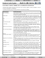
ELECTRONIC CONTROL TERMINOLOGY & COMPONENT DESCRIPTIONS

The Built-In Series utilizes an electronic control system which monitors, regulates, controls and displays a variety of
functions and operations in the appliance.

The table below defines some of the basic electronic control system terminology.

Previous Page

Next Page

Main Menu

Built-In Series Menu

Built-In Series Menu

Previous Page

Main Menu

Table of Contents

Next Page

Summary of Contents for BI-36UG

Page 1: ...cators The words numbers and icons that appear at the LCD Fault Codes Error Codes The code number indicators that may appear in the LCD when accessing Fault Code History during Fault and Sensor Recall...

Page 2: ...REF EVAPORATOR FAN FREEZER EVAPORATOR FAN M M FLOW METER THERMISTER FREEZER EVAP THERMISTER FREEZER CABINET THERMISTER REF CABINET THERMISTER REF EVAP BROWN BLACK WHITE WHITE BLACK BLUE BROWN BLUE BRO...

Page 3: ...VE POWERS IM WATER VALVE UNUSED UNUSED UNUSED UNUSED UNUSED UNUSED UNUSED FUNCTION WHITE BLUE ORANGE RED GRAY WHITE ORANGE BLACK PINK WHITE RED RED TAN ORANGE BLACK WHITE BLACK BLUE YELLOW PURPLE GRAY...

Page 4: ...have the refrigerator zone COLDER and WARMER keys nor the PURE AIR key The control panel keys are capacitance touch sensitive so even though the words press is used throughout this section to indicate...

Page 5: ...hts are energized double dashes appear in the LCD followed by the model code then all components are switched OFF and the word OFF appears in the LCD See Figure 3 5 By pressing the POWER key for one 1...

Page 6: ...s allowed to the ice maker system and the single ice cube icon appears in the LCD See Figure 3 8 To switch the ice maker system OFF press the ICE MAKER key again and the single ice cube icon disappear...

Page 7: ...wenty four 24 hours switching off only when the door is opened After twenty four 24 hours the freezer set point reverts to the last manually input set point the freezer evaporator fan resumes its norm...

Page 8: ...note that this is not intended to be an air deodorizer but rather a devise that helps to preserve foods for longer storage life by remov ing these food storage by products To activate the air purifica...

Page 9: ...five 5 seconds then release the keys See Figure 3 13 a c will appear at the upper right of the temperature readings in the LCD indicating that temperatures will now be displayed in Celsius units of me...

Page 10: ...slanting at slightly differ ent angles for each level adjustment This means that the lower numbers will not always indicate less contrast and the higher numbers will not always indicate more contrast...

Page 11: ...ime will sound in the lower softer tone while pressing a WARMER key will increase the tone setting and the chime will sound in the higher louder tone See Figures 3 19 and 3 20 NOTES Do not press and h...

Page 12: ...pened or the PURE AIR key is pressed The lighting system will be disabled for twenty 20 minutes if the lights stay ON more than 90 of the time in any given fifteen 15 minutes or if a compartment therm...

Page 13: ...ccompanied by two beeps and current zone temperature will appear in the LCD NOTES Set points cannot be changed and manual defrost cannot be initiated The following holds true in accordance with Star K...

Page 14: ...ed zone to operational state repeat the steps above NOTE If switched OFF then back ON the electronic control stores this mode set in non volatile memory so the disabled zone will remain disabled until...

Page 15: ...t temperatures will be displayed See Figure 3 29 NOTES Though the refrigerator evaporator temperature is also shown when manual defrost is initiated only the freezer evaporator is affected Manual Free...

Page 16: ...s and the dis penser will meter out the ice collect it in the cylinder valve directly above the glass then turn the cylinder valve to drop the ice into the glass See Figure 3 32 If less ice is desired...

Page 17: ...key on the main control panel to switch the unit OFF then back ON To deactivate or reactivate this feature within the first minute after switching the unit ON 1 Press the LIGHT key on the dispenser c...

Page 18: ...power to the freezer evaporator fan and the icemaker is interrupted If in Sabbath Mode the lighting system is disabled Figure 3 37 Signal Trace Schematic Lighting System 115 VOLTS 60 CYCLES L1 NEUTRAL...

Page 19: ...OOR SWITCH REF DOOR SWITCH ISOLATION VALVE 660 WATER VALVE 160 M IM CONDENSER FAN MOTOR CRISPER LIGHTS REF LIGHTS AIR FILTER LIGHT FREEZER LIGHTS FILL TUBE HEATER 2300 2900 DEF HEATER 27 9 30 9 DEFROS...

Page 20: ...25 second delay before the cooling cycle is started The condenser fan is ener gized whenever a compres sor is energized 115 VOLTS 60 CYCLES L1 NEUTRAL N O WATER FILTER SWITCH P16 MAIN CONTROL BOARD P1...

Page 21: ...els if the refrigerator door is opened while the evaporator fan is operating the microprocessor will detect the power signal to the lights and interrupts the 12V DC power to the fan See Figure 3 40 NO...

Page 22: ...DEFROST HTR COMP2 COMP1 MAIN LIGHTS N C N C FZ DOOR SWITCH REF DOOR SWITCH ISOLATION VALVE 660 WATER VALVE 160 M IM CONDENSER FAN MOTOR CRISPER LIGHTS REF LIGHTS AIR FILTER LIGHT FREEZER LIGHTS FILL T...

Page 23: ...tarted 115 VOLTS 60 CYCLES L1 NEUTRAL N O WATER FILTER SWITCH P16 MAIN CONTROL BOARD P1 3 P14 L1 L1 NEUTRAL 1 1 6 4 P2 P15 8 5 P3 P6 P5 P6 P9 P8 P7 P18 DEFROST HTR COMP2 COMP1 MAIN LIGHTS N C N C FZ D...

Page 24: ...2300 2900 DEF HEATER 27 9 30 9 DEFROST TERMINATOR REFRIGERATOR COMPRESSOR STARTING RELAY FREEZER COMPRESSOR STARTING RELAY PURPLE WHITE WHITE BLUE WHITE BLUE BLUE WHITE PURPLE GRAY RED PINK YELLOW BL...

Page 25: ...in Sabbath Mode the com partment thermistor still controls compressor oper ation except that when high offset is reached there is a random 15 to 25 second delay before the com pressor is energized The...

Page 26: ...n be ramped down to low speed during the compressor off cycles See Figure 3 45 NOTE During Sabbath Mode the lighting system is disabled and the 12V DC supplied to the evaporator fan cannot be interrup...

Page 27: ...efrost duration 30 minutes plus 5 minute dwell If the defrost sensing line to P18 6 is open defrost operation defaults to 25 minute defrost heater ON time 6 hour build time and the appropriate fault c...

Page 28: ...tton was pressed then the water filter icon in the LCD will illuminate See Figure 3 47A indicating it is time to change the filter Figure 3 47 Signal Trace Schematic Flow Meter Monitored Filter Reset...

Page 29: ...to the ice maker system for an additional three 3 minutes unless the Maximum Ice Production feature has been initiated When in Sabbath Mode the ice maker system is disabled The ice maker sys tem is d...

Page 30: ...ault indicator reappearing in the LCD when the unit is switched back ON Figure 3 50 Signal Trace Schematic Monitoring Compressor Run Times 115 VOLTS 60 CYCLES L1 NEUTRAL N O WATER FILTER SWITCH P16 MA...

Page 31: ...them in a glass of ice water 32 F 0 C for approximately five 5 minutes then checking for 30 000 to 33 000 ohms To clear fault indicators and Fault Codes See Figures 3 54 to 3 59 the problem must be c...

Page 32: ...igure 3 56 Service Icon and Ice Cube Icon Flashing Solenoid Energized 35 Seconds and Ice Maker System was Disabled for 24 Hours 5 Consecutive Times now Ice Maker System Disabled until Repaired PURE AI...

Page 33: ...press the POWER key then release both keys If there are no Fault Codes logged then at left in the LCD will be current real time temperature readings of a thermistor at right will be the thermistor loc...

Page 34: ...present See Figure 3 64 There is currently no thermistor in the drawers so EE will appear at left of the dr See Figure 3 65 There is currently no thermistors on the condenser so EE will appear at lef...

Page 35: ...lowing pages NOTE Do not press and hold the COLDER and POWER keys for more than ten 10 seconds as this will initiate Manual Zone Component Activation Mode which is covered later in the section Fault C...

Page 36: ...Refrigerator Evaporator Water Systems 00 01 02 05 06 07 09 10 11 12 20 21 22 25 30 33 34 35 36 37 38 39 40 42 43 44 45 46 Open Short Closed Unstable Miswire normal temps Miswire overheat Bad Ohms Too...

Page 37: ...gh Voltage System Lighting Refrigerator Evaporator Water Systems 50 55 56 60 65 66 70 71 72 73 74 75 80 81 82 83 84 85 86 87 90 92 93 95 96 97 98 99 Open Heater Triac Open Triac Short No Load Load Ope...

Page 38: ...se a WARMER or COLDER key to toggle through the readings until the desired thermis tor location code is displayed See Figure 3 70 r Refrigerator rE Refrigerator Evaporator F Freezer FE Freezer Evapora...

Page 39: ...de Flashes at 3 second intervals F then E Freezer Evaporator Figure 3 72 Thermistor Location Code Flashes at 3 second intervals F then E Freezer Evaporator PURE AIR WARMER COLDER WARMER COLDER ALARM P...

Page 40: ...ature Log Event Indicators The diagrams below illustrate possible event indicators that may be observed while in Temperature Log Recall Mode See Figures 3 76 through 3 78 PURE AIR WARMER COLDER WARMER...

Page 41: ...ARMER or COLDER key in multiple key strokes until the appropriate model code is displayed See Figures 3 82 and 3 83 With the appropriate model code displayed press the POWER key and Pr and g appear in...

Page 42: ...COLDER WARMER COLDER ALARM POWER MAX ICE ICE MAKER LIGHTS Figure 3 83 Stop When Correct Model Code is Displayed 00 and 3 48 Side by Side PURE AIR WARMER COLDER WARMER COLDER ALARM POWER MAX ICE ICE M...

Page 43: ...omponent while the COLDER key would activate a previous step component See Manual Component Activation Tables on next page NOTE All temperatures displayed are current real time temperatures without we...

Page 44: ...ights ON Air Purifier Light Fan ON Ar Ft Displayed Everything OFF Light relay ON Lights OFF OFF Displayed All Lights OFF Main Lights ON LS On Displayed Main Lights ON All else OFF Accent Display Light...

Page 45: ...ive 5 seconds during which tE St will be displayed in the LCD At the end of the self test the current compartment temperature readings will appear in the LCD When Self Test Mode does end it will be ne...

Reviews: