7 Teleservice Application Framework
User Manual
110/374
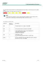
The following states can be displayed:
State of the module
LED color
Description
Power ON
yellow
This state is active when the TC3G has booted
and none of the other states are active.
GPS
blue
This state is active when ygpsd is activated and a
valid NMEA string is received and the internet-
state is not active.
Internet
pink
This state is active when ynetworkd is activated
and a valid connection to the internet exists and
the GPS-state is not active. This is also verified
by a ‘ping’ signal or a file download.
GPS + Internet
green
This state is active when the ‘GPS’ state and the
‘Internet’ state are both active.
CAN traffic
flashing LED, without changing
its color
This state is active when there is traffic on CAN0
or CAN1.
Error
blink code initialized by a 'red'
LED signal
This state is active when a ‘Goodbye’ signal from
a daemon is received or when a valid entry in the
/tmp/LED_Error file exists.
User
blink code initialized by a pause
of the LED signal
This state is active when a valid entry in the
/tmp/LED_User file exists.
The signal daemon checks if the variant supports:
GPS
GSM
WLAN
BT
If the variant does not support GPS, then the 'GPS + Internet' state will never be reached. Therefore, the color
of the 'Internet' state is set to 'green'.
NOTE:
The 'CAN traffic' state will not be signalized when the 'Error' state is active.
The 'User' state is signalized parallel to all other states.
NOTE:
If the LED signal is 'green', all possible states, depending on the variant, are reached.
Summary of Contents for TC1
Page 1: ...TC1 User Manual Version of this document V1 00r0 ...
Page 25: ...5 Hardware User Manual 25 374 5 2 2 Block Diagram Variant TC1 WIFI ...
Page 34: ...5 Hardware User Manual 34 374 5 6 Housing Connector Top view and side view Bottom View ...
Page 125: ...7 Teleservice Application Framework User Manual 125 374 TAF overview ...
Page 190: ...7 Teleservice Application Framework User Manual 190 374 How the logger mechanism works ...


