background image

Model 5402 User Guide 

Issue 3, August 2021 

Studio Technologies, Inc. 

Page 31

Model 5402


DANTE LEADER CLOCK WITH GNSS SYNCHRONIZATION

Menu Text and Links

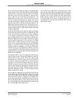
The following provides details on some of the text and links 

that are presented on the Model 5402’s webpages.

Device Name:

 In the upper-right corner of each Model 

5402 webpage is the Dante device name. This name is 

unique to each device in a Dante deployment and is used 

as part of the Dante subscription (channel routing) process. 

The name can be changed from within the Dante Controller 

application.

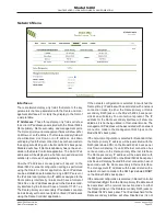
Identify Device Link:

 In the upper-right corner of each 

webpage, directly below the device name, is a link called 

Identify Device. Clicking on it will cause the Dante identify 

action to commence on the specific Model 5402. The action 

will consist of the front-panel display’s green backlight flash-

ing five times. This command will help confirm that the web 

server on the desired Model 5402 is being accessed.

Company Name Link:

 On the bottom of each webpage 

is a link with the title Studio Technologies, Inc. Clicking on 

this link will cause the browser to open the Home webpage 

of the Studio Technologies website.

Log Out Link:

 In the upper-right corner of most of the 

Configuration menu webpages is a link called Log Out. It 

will cause the Model 5402’s web server to end the session, 

logging out the user and returning to the Home menu. To 

again access the configuration webpages requires that the 

user click on the Login tab and provide a valid user name 

and password.

Operation

Now that the Model 5402 is installed and configured it’s 

ready for use. The unit is designed for continuous, unat-

tended operation. However, there are a number of nuances 

in the unit’s operation. This may make it worthwhile for 

personnel to spend some time reviewing this section.
Upon application of AC mains or DC power, the Model 5402 

will go through a power-up sequence. The nine bi-color 

LEDs on the Model 5402’s front panel will light green, then 

light red in a confirmation sequence. The unit’s graphics 

display will show the Studio Technologies logo graphics 

image, followed by a menu page that shows the product 

name (Model 5402) and the Dante name. Then the version 

number of the Main MCU firmware will display. After a few 

seconds the screen saver mode, detailed later in this sec-

tion, will begin operation.
Upon power being applied the green LED adjacent to the 

USB receptacle on the back panel will flash once to indicate 

that its associated circuitry is performing correctly. Also, 

upon power being applied to the Model 5402 the LEDs on 

the back panel associated with the unit’s three Ethernet 

RJ45 jacks will briefly flash as a functional test.

After the Model 5402 has completed its power-up se-

quences the unit will begin operation. The nine front-panel 

LEDs will reflect the real-time status of the unit’s major 

functions. The front-panel display will allow the viewing 

of over 25 menu pages showing status and configuration 

conditions. In addition, using the front-panel pushbutton 

switches some of the unit’s configuration settings can be 

revised as required.
The following paragraphs will detail the operation of the 

front-panel LEDs.

Power LEDs

Two LEDs indicate the presence of incoming AC mains 

and nominal 12 volts DC power. They are labeled AC and 

DC and can light green or red. When a source of AC mains 

power is connected the AC LED will light green. (This is 

actually in response to 12 volts DC that is being gener-

ated by the internally located AC mains input/12 volts DC 

output power supply.) The LED labeled DC will light green 

whenever a connected DC source exceeds approximately 

10 volts. The DC LED will light red when the DC input is 

between approximately 9 and 10 volts, indicating a low-volt-

age condition. Once the DC input is less than approximately 

9 volts the DC LED will not light and the Model 5402 will 

no longer operate from the DC source.

Network LEDs

Three LEDs provide status indications related to the Model 

5402’s three Ethernet network interfaces. Two of the LEDs 

are associated with the Model 5402’s Dante primary and 

Dante secondary Ethernet ports. They are labeled PRI 

and SEC. The third LED, labeled MGMT, is associated 

with the unit’s management Ethernet port. The way in 

which the three Ethernet interfaces and their associated 

status LEDs function depend on the network configuration 

as selected using the Dante Controller application. The 

choices are Switched, Redundant, SMgmt, and 

ReMgmt.

Switched Network Operation

PRI LED: The PRI LED will light red when no Ethernet 

connection is present on the Dante primary or Dante 

secondary Ethernet ports. It will light green whenever a 

Gigabit Ethernet connection is present on either the Dante 

primary or the Dante secondary Ethernet port and a link 

has been established. It will light orange whenever a 100 

Mb/s Ethernet connection is present on either the Dante 

primary or the Dante secondary Ethernet port and a link 

has been established.
SEC LED: The SEC LED will not light.
MGMT LED: When no Ethernet connection is present on 

the management Ethernet port the MGMT LED will not light. 

Summary of Contents for Dante 5402

Page 1: ...chnologies Inc all rights reserved studio tech com User Guide Issue 3 August 2021 This User Guide is applicable for serial numbers M5402 00151 and later with Main MCU Firmware 1 01 and later Model 540...

Page 2: ...This page intentionally left blank...

Page 3: ...ration 13 Operation 31 Technical Notes 39 Specifications 43 Appendix A Compatible Sync Input Sources 45 Appendix B Network Configuration Examples 46 Appendix C Dante Controller Network Default Configu...

Page 4: ...YNCHRONIZATION Revision History Issue 3 August 2021 Revises format of document Incorporates menu page screen captures in line with text and removes related appendix Issue 2 July 2021 Documents support...

Page 5: ...capabilities two Model 5402 units can serve in primary and backup Leader clock roles for redundant operation Figure 1 Model 5402 Dante Leader Clock with GNSS Synchronization front and back views The...

Page 6: ...y identified as being received from a GNSS Global Navigation Satellite System GPS Global Positioning System is just one set of satellites that can provide GNSS data For maximum flexibility the Model 5...

Page 7: ...ived time base are rarely if ever supported PTP performance can degrade when the computing power of a device is intended primarily for han dling and manipulating digital audio signals This can lead to...

Page 8: ...a detachable cord that is compatible with the unit s 3 pin IEC 320 C14 inlet connector Some applications may warrant connection to a source of nominal 12 volts DC which can be made by way of a 4 pin...

Page 9: ...e rate can be 44 1 48 88 2 96 176 4 or 192 kHz If termination has been enabled for the sync input when it has been configured for word clock an impedance of 75 ohms will be applied A source of bi leve...

Page 10: ...e provided by an Ethernet switch Switched mode is the default setting but using the Dante secondary port in this manner for applications other than troubleshooting or looping to access the Model 5402...

Page 11: ...ly be done with the Dante Controller software application available for download free of charge at audinate com Refer to Appendix C of the list of the Model 5402 s Dante Controller default configura t...

Page 12: ...ither the Switched or Switched Mgmt network mode a single Dante IP address will be associated with the network connec tion that is made to either the Dante primary or the Dante secondary RJ45 jack If...

Page 13: ...address be continuously displayed then the Enter pushbutton switch on the front panel should be pressed This will stop the screen saver function and cause the current management IP address to display...

Page 14: ...d will display which timing source is actively being utilized by the Model 5402 The GNSS status field will indicate the current condition of the Model 5402 s GNSS satellite receiver The Sync Input sta...

Page 15: ...able user name and or password be misplaced refer to the Technical Notes section and or Appendix G of this guide for a recovery method User Name Enter the Model 5402 s user name into this field It is...

Page 16: ...ellation or constellations will be used This would be assuming that a solid GNSS lock can be established the most accurate and consistent timing source It s expected that GNSS will be selected in most...

Page 17: ...red Leader by unchecking the Model 5402 s Preferred Leader check box in Dante Controller After a short interval the box will automatically return to the enabled checked state How the Model 5402 handle...

Page 18: ...d a valid source has not been connected to the sync input It simply indicates that the sync input circuitry is not actively receiving an external signal Primary Leader Clock A display only field will...

Page 19: ...upport is not enabled then Disabled will show in the primary PTPv2 field Since Dante secondary is not enabled then the secondary PTPv1 and secondary PTPv2 fields will show Disabled If the Model 5402 s...

Page 20: ...put This would typically indicate a short circuit associated with the SMA plug and cable that is used to link the Model 5402 with the antenna Number of Satellites This field shows the number sat ellit...

Page 21: ...e or more satellites However unchecking one or more of the boxes will allow selection of the constellations that are desired for a specific application There is no problem selecting even just one cons...

Page 22: ...a non compatible signal is connected A non compatible signal would include a sync input type be ing selected for Word Clock and then a word clock signal at a different rate than the current Dante samp...

Page 23: ...Model 5402 s circuit design The unit s logic circuitry has to perform the least amount of processing with a word clock input signal as compared to that required to utilize a video reference or a 10 MH...

Page 24: ...000 or 10000 Hz reference sine wave tones and there s no problem configuring these if desired Level dBFS These eight fields display the level of the Model 5402 s sine wave tone outputs The output leve...

Page 25: ...ante primary and secondary IP addresses can also be individually set to a manual static or fixed IP addresses using the Dante Controller application If the network configuration is selected for switch...

Page 26: ...te secondary and management ports These are fixed hardware addresses assigned to Ethernet ports Each is unique among all Ethernet ports and cannot be changed The Model 5402 displays MAC addresses as s...

Page 27: ...t Mask Value This field shows the stored subnet mask value associated with the management web server when the manual mode has been selected for the IP address configuration When IP address configurati...

Page 28: ...guest These are case sensitive If neither of the default entries are changed then they will display in the user name and password entry fields on the Login menu webpage If the default user name and o...

Page 29: ...e Main FPGA Firmware This display only field that shows the version number and associated date of the Model 5402 s Main FPGA field programmable gate array firm ware This firmware can be field updated...

Page 30: ...the network configuration or user name and password settings For the defaults to be restored the associated check box must be enabled prior to pressing the Submit button Be careful when using this fu...

Page 31: ...its associated circuitry is performing correctly Also upon power being applied to the Model 5402 the LEDs on the back panel associated with the unit s three Ethernet RJ45 jacks will briefly flash as...

Page 32: ...is present on the Dante secondary Ethernet port and a link has been established It will light orange whenever a 100 Mb s Ethernet connection is present on the Dante secondary Ethernet port and a link...

Page 33: ...not be lit If the unit s main clock source has been configured to utilize an external source of sync then the LED will light green if a valid source has been connected The SYNC IN LED will light red i...

Page 34: ...Main webpages the status of the Dante primary and Dante secondary interfaces including their support for PTPv1 and PTPv2 will be displayed Current Clock Source This menu page will display which timing...

Page 35: ...5402 performed a bootup restart and when the GNSS receiver first established a fully locked condi tion Subsequent reboots of the GNSS receiver will not cause a new TTFF value to be stored Technically...

Page 36: ...can be modified as desired This will be indicated by a circle with arrows icon that will show in the upper right corner of the display To start the process of changing the manual management IP address...

Page 37: ...g the reboot system menu page us ing a function on one of the management webpages or by power cycling the Model 5402 Note that to minimize the chance of losing access to the Dante network restoring th...

Page 38: ...he Enter pushbutton on the unit s front panel This will lead to a confirmation page being displayed Use the left and right arrow pushbut ton switches to select the desired action The choices are to ca...

Page 39: ...file The Model 5402 will provide support for PTPv2 if the AES67 mode has been enabled in the Dante Control ler application This is in addition to PTPv1 support both can function simultaneously When AE...

Page 40: ...Ethernet IP address and related network parameters can be set to a manual fixed or static configuration The first method uses the front panel display and buttons to allow the management Ethernet netwo...

Page 41: ...o determine the version of the firmware embedded software that resides in the Brooklyn II mod ule The System webpage provided by the Model 5402 s management web server can also be used to identify the...

Page 42: ...Bay where compatible antennas ranged in price from about US 50 up to several thousand dollars When selecting an alternate antenna there are a number of parameters that have to be taken into account Th...

Page 43: ...e wave 5 Vpp nominal unloaded 44 1 48 88 2 96 176 4 or 192 kHz Video Signal Compatibility bi or tri level 1 Vpp nomi nal into 75 ohm load 10 MHz Signal Compatibility sine wave 3 Vpp nominal into 50 oh...

Page 44: ...jack Sync Input Word Clock Output 2 BNC jack female connector per IEC 61169 8 Annex A Ethernet 3 RJ45 jack USB type A receptacle used only for updating firmware DC Input 4 pin male XLR pin 1 negative...

Page 45: ...ignals Word Clock Square wave signal with rate of 44 1 48 88 2 96 176 4 and 192 kHz 10 MHz Sine wave signal with an amplitude of 1 Vrms nominal terminated with 50 ohms Bi Level and Tri Level Video See...

Page 46: ...Issue 3 August 2021 Model 5402 User Guide Page 46 Studio Technologies Inc Model 5402 DANTE LEADER CLOCK WITH GNSS SYNCHRONIZATION Appendix B Network Configuration Examples...

Page 47: ...Model 5402 User Guide Issue 3 August 2021 Studio Technologies Inc Page 47 Model 5402 DANTE LEADER CLOCK WITH GNSS SYNCHRONIZATION...

Page 48: ...Issue 3 August 2021 Model 5402 User Guide Page 48 Studio Technologies Inc Model 5402 DANTE LEADER CLOCK WITH GNSS SYNCHRONIZATION...

Page 49: ...Interface Default Values Device Config Sample Rate 48k Device Config Clocking Unicast Delay Requests Disabled Device Config Device Latency Latency 1 0 msec Network Config Switch Configuration Current...

Page 50: ...Issue 3 August 2021 Model 5402 User Guide Page 50 Studio Technologies Inc Model 5402 DANTE LEADER CLOCK WITH GNSS SYNCHRONIZATION Appendix D Menu Structure...

Page 51: ...25 dBFS Tone 6 Frequency 600 Hz Level 26 dBFS Tone 7 Frequency 700 Hz Level 27 dBFS Tone 8 Frequency 800 Hz Level 28 dBFS Network Menu Management Interface IP Address Configuration Automatic Manual I...

Page 52: ...tics Notes 1 For Model 5402 PTPv2 support to be active AES67 compatibility check box must be enabled in Dante Controller application 2 These default configuration characteristics apply to both the Dan...

Page 53: ...ence release the two buttons 6 Use a web browser to access the Model 5402 s Configuration menu webpages The management port s IP address to use is shown in the current management IP address page on th...

Reviews: