background image

Installation, Operation & Maintenance 
Instructions

Please leave this instruction booklet with the owner as 
it contains important guarantee, maintenance and safety 
information

Read this manual carefully before commencing installation.

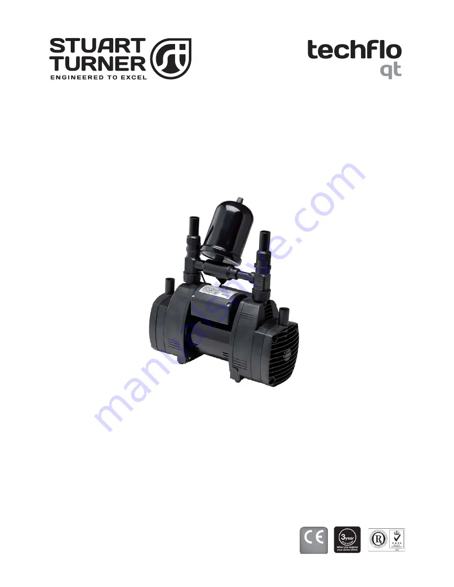
This manual covers the following products: 

U2.3 bar Single

Pt. No. 49082

U2.3 bar Twin

Pt. No. 49080

U3.3 bar Single

Pt. No. 49083

U3.3 bar Twin

Pt. No. 49081

FOR POSITIVE OR NEGATIVE HEAD APPLICATIONS

CE compliant product

Summary of Contents for 49080

Page 1: ...rtant guarantee maintenance and safety information Read this manual carefully before commencing installation This manual covers the following products U2 3 bar Single Pt No 49082 U2 3 bar Twin Pt No 49080 U3 3 bar Single Pt No 49083 U3 3 bar Twin Pt No 49081 FOR POSITIVE OR NEGATIVE HEAD APPLICATIONS CE compliant product ...

Page 2: ... of experience and knowledge if they have been given supervision or instruction concerning use of the appliance in a safe way and understand the hazards involved Children shall not play with the appliance Cleaning and user maintenance shall not be made by children without supervision Children should be supervised to ensure that they do not play with the appliance Please read installation details c...

Page 3: ...ve are for twin pumps single pumps are shown in brackets Fig 1 Twin pump shown 22 mm isolation valve non restrictive not supplied To allow easy service of pump 22 mm inlet pipework 22 mm inlet pipework 22 mm outlet pipework A B B C IMPORTANT With the pump removed from its packaging check for any damage prior to installation If any damage is found contact Stuart Turner Ltd within 24 hours of receip...

Page 4: ...assembly and gently push the threaded area at the bottom onto the plastic nut 4 Rotate the plastic nut anti clockwise viewed from the top Ensure the plastic nuts are tightened evenly on twin pumps 5 Fully tighten by hand 6 Fit the sealing washer and hand tighten the pressure vessel Fig 3 Care must be taken when fitting the pressure vessel not to cross thread on assembly Do not overtighten the pres...

Page 5: ...ge will void any warranty 1 18 Pipework design Care should be taken in the design of pipework runs to minimize the risk of air locks e g use drawn bends rather than 90o bends 1 19 DO NOT introduce solder flux to flexible hoses pumps or pump parts manufactured from plastic 1 20 DO NOT allow contact with oil or cellulose based paints paint thinners or strippers acid based descalents or aggressive cl...

Page 6: ...p must be sited in a location where the maximum ambient temperature does not exceed 40 o C 2 19 Pipework For optimum performance pipework MUST be 22 mm Pipework should only reduce to 15 mm when entering terminal fitting 2 20 Static outlet pressure The static outlet head must also be within the maximum requirement see Figs 4 5 2 21 Noise The anti vibration mounting feet and flexible hoses which are...

Page 7: ...IR FREE supply via a tank connector and must be positioned at a slightly lower level 25 mm minimum than the feed pipe to the hot water cylinder Do not connect to the mains Positive Duty Single Pump System Fig 4 Static outlet Pressure Max 6 m Max inlet head 6 m Min inlet head 0 5 m ...

Page 8: ...No 27900 2 28 Expansion pipe When the method of connection is to be made via the expansion pipe the cold water storage cistern should be at least 1 metre above the top of the hot water cylinder 2 29 Location The pump must for optimum performance be sited as close as possible to and never more than 4 metres from the HOT WATER cylinder The pump should always be sited BELOW the HOT WATER take off fro...

Page 9: ...s are in place Outlet use hoses suppled with no isolating valves and follow same process 3 12 Hose to pipework 1 These plastic push in connectors must only be connected with the following a 22 mm diameter copper pipe to BS EN 1057 R250 half hard Table 3 b 22 mm plastic pipe to BS 7291 part 1 and part 2 Table 1 or part 3 Table 1 plus internal support sleeve The internal bore of the plastic pipe mus...

Page 10: ...care should be taken to isolate pump and towels used to absorb spilled water 3 13 Typical Low Level Installation In certain installations it may be necessary to install a 90 bend on the inlet or outlet connections of the pump before the flexible hose to accommodate a low level installation For this purpose use a 22 mm stem elbow not supplied If you have any concern either about using push in fitti...

Page 11: ...e supplementary earth bonding where the continuity has been broken by flexible hoses or plastic components 4 18 Additional earthing Certain installations may require additional earthing arrangements such as equipotential bonding Reference should be made to the relevant regulations concerning this subject to ensure compliance 4 19 Connections The pump must be permanently connected to the fixed wiri...

Page 12: ...hich is marked with the letter N or coloured black The wire which is coloured brown must be connected to the terminal which is marked with the letter L or coloured red 4 21 Fuses The following fuse size should be used with the appropriate pump Model Fuse Size AMPS All models 5 ...

Page 13: ...n pump dry 5 13 Priming starting a Ensure all outlets are closed turn power supply on pump will start pressurise the system then stop b Open the shower valve or terminal fitting and with shower head in its lowest position switch on the power supply to the pump for 5 10 seconds and then switch off again Allow a further 30 seconds of gravity flow before switching the pump on to run for 10 seconds Re...

Page 14: ...rainers may require periodical cleaning The frequency of this operation is dependent upon installation conditions The strainer is located in the inlet assembly of the pump casing and is removed as follows a Isolate pump electrically b Release all system pressure c Isolate hot and cold water supplies via the integral pump isolating valve located in the flexible hoses and release hoses by holding th...

Page 15: ...g periods The pump must be run for at least 5 minutes every four weeks to exercise all working parts Run on cool water See Section 7 Technical Specification for note on water temperature This particularly applies to guest bathrooms used infrequently 6 16 Cleaners Disinfectants and Descalents Acid based descalents and aggressive cleaning agents must not come into contact with the pump The pump must...

Page 16: ...uction Power consumption 540 Watts 820 Watts 290 Watts 410 Watts Full load current 2 4 Amps 3 6 Amps 1 2 Amps 1 8 Amps Rating Intermittent 30 mins on 30 mins off 20 l min Intermittent 30 mins on 30 mins off 20 l min Intermittent 30 mins on 30 mins off 20 l min Intermittent 30 mins on 30 mins off 20 l min Max No Starts per hour 60 60 60 60 Mechanical Max inlet head 6 metres 6 metres 6 metres 6 metr...

Page 17: ... No hot water Air locked water feed Vent hot water pump of air Check cold feed to hot water cylinder Check water level in cold water tank and that all stopcocks and isolating valves are open Heat source not operating Check boiler is switched on Check cylinder thermostat Check immersion heater Check cylinder contains hot water All hot water has been used Check tank volume is adequate Faulty thermos...

Page 18: ...e the following information 1 Full pump serial number including last 3 digits which can be found on the pump rating label and the back page of the installation instructions 2 Your name address telephone e mail 3 The date of installation Within the guarantee period we will repair free of charge any defects in the pump resulting from faults in material or workmanship repairing or exchanging the whol...

Page 19: ...ity to quickly locate an installer in their area Registration is free simply click on the register as an installer link on our homepage at www stuart turner co uk and complete a short form which will enable visitors to find your contact details on our web site installer finder Alternatively use your smartphone to scan this QR code and go straight to the form We ll do the rest In addition we will e...

Page 20: ...TOR DRIVEN PUMP AS SERIAL NUMBER BELOW COMPLIES WITH THE ESSENTIAL REQUIREMENTS OF THE ABOVE E E C DIRECTIVES RESPONSIBLE PERSON AND MANUFACTURER STUART TURNER LIMITED HENLEY ON THAMES OXFORDSHIRE RG9 2AD ENGLAND Signed Business Development Director Stuart Turner are an approved company to BS EN ISO 9001 2000 Stuart Turner Ltd Henley on Thames Oxfordshire RG9 2AD ENGLAND Tel 44 0 1491 572655 Fax 4...

Reviews: