27
9 ELECTRICAL INSTALLATION
9.1 General
•
For operation, the boiler needs a power supply of 230 VAC 50Hz.
•
The boiler main supply connection is phase/neutral sensitive.
•
The wiring for the connections can be entered at the bottom of the boiler through the cable glands.
•
NOTICE: Before starting to work on the boiler, it must be switched off and the power supply to the boiler
must be disconnected.
•
Electrical wiring should be installed according to all applicable standards and regulations.
•
Working on the boiler should only be done by a qualified service engineer that is skilled in working on
electrical installations and according to all applicable standards.
9.2 Connection mains supply
•
It is advised to use a flexible cable between the cabinet entry (at the bottom) and the connection terminal.
•
The earth wire has to be longer than the phase and neutral wire.
•
The power supply cable must be secured by tightening the cable gland at the bottom of the boiler casing.
•
In case of a flexible cable: use crimp ferrules on each wire end for the terminal connections.
•
The minimum cross section of the wires in the power supply cable is 3 x 1.0 mm
2
.
•
As it is a stationary appliance without means for disconnection from the supply a contact separation in all
poles that provide full disconnection under voltage category III must be provided.
9.3 Electrical connections
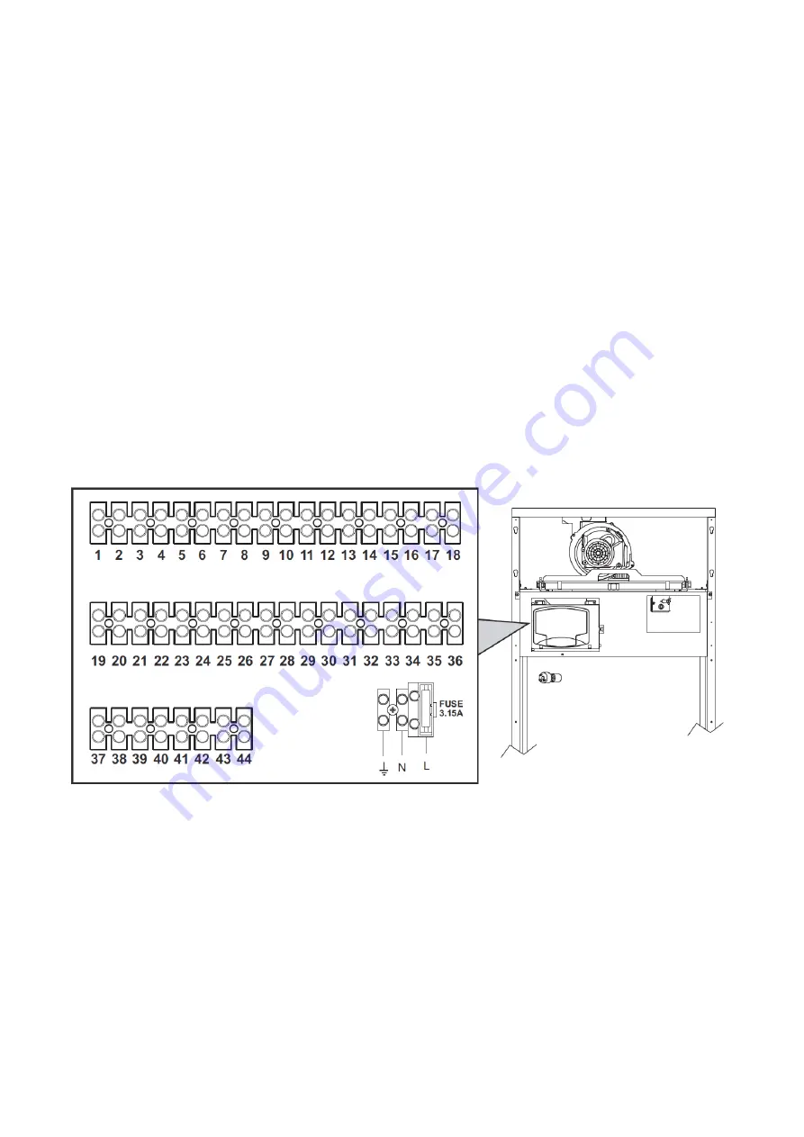
The electrical terminal block is located in the rear of the control panel.
The S-FX boiler is prewired and provided with a Y-cable and plug for connection to the electrical supply. The
connection to the mains power supply must be made with a permanent connection and equipped with a bipolar
switch whose contacts have a minimum opening of at least 3mm, interposing fuses of max 3A between the boiler
and the mains supply panel.
It is important to respect the polarities:
•
Power Live Supply = Brown.
•
Neutral = Blue.
•
Earth = Yellow & Green.
During installation or when changing the power cable, the earth wire must be left 2cm longer than the others.
Summary of Contents for S-FX 125
Page 2: ......
Page 11: ...11 4 BOILER DIMENSIONS 4 1 S FX 70 4 2 S FX 125 ...
Page 12: ...12 4 3 S FX 220 4 4 S FX 320 ...
Page 28: ...28 9 4 Electrical Schematics S FX 70 ...
Page 29: ...29 S FX 125 ...
Page 30: ...30 S FX 220 320 ...
Page 67: ...67 BLANK PAGE ...


