background image

13


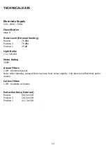
TECHNICAL DATA


Electricity Supply


230 - 240V ~ 50Hz


Classification


class II


Noise Level (External Venting)


Booster 

70 dBA


Position 3 

70 dBA


Position 1 

49 dB


Light Bulbs


2 x 1.5W LED


Motor Rating


203W


Grease Filters


2 Off - Aluminium panel


Note: After cleaning, grease filters may lose their colour slightly - this does not affect their perfor- 
mance.


Carbon Filters


2 Off - Available as Spares


Extraction Rate (External)


Booster 

582.6 m3/H


Position 3 

582.6 m3/H


Position 1 

411.3 m3/H


Summary of Contents for 444410718

Page 1: ...Stoves Cooker Hood User Manual ...

Page 2: ...2 Contents Introduction 4 Safety Precaution 5 Installation Instructions 6 Using the Hood 10 Care and Cleaning 12 Technical Data 13 Stoves Customer Care 14 ...

Page 3: ... ducting kit or carbon filters Details for orde ring these parts are at the back of the handbook Because of the complexity and weight of the appliance it is recommended that the installation be carried out by specialist personnel The manufacturer declines all responsibility for damage caused by improper or installation Please read this handbook carefully and keep it for future reference Your first...

Page 4: ...areas during or straight after prolonged use of the lighting installation C Flambè cooking is prohibited underneath the cooker hood D Avoid free flame as it is damaging for the filters and a fire hazard E Do not leave food frying unattended as the overheated oil may become a fire hazard F Disconnect the electrical connection prior to any maintenance G This appliance is not intended for use by youn...

Page 5: ...t must be placed outside the lower part Fig 3 Do not connect the cooker hood exhaust to the same conductor used to circulate hot air or for evacuating fumes from other appliances generated by other than an electrical source Before proceeding with the assembly operations remove the anti grease filter s Fig 1 so that the unit is easier to handle In the case of assembly of the appliance in the suctio...

Page 6: ... the wall and align it in horizontal position to the wall units When the appliance has been adjusted definitely fix the hood using the screws B Fig 3 For the various installations use screws and screw anchors suited to the type of wall e g reinforced concrete plasterboard etc If the screws and screw anchors are provided with the product check that they are suitable for the type of wall on which th...

Page 7: ... the screws A Fig 5 in such a way that it is in line with your hood and respecting the distance from the ceiling Connect the flange C to the air exhaust hole using a connection pipe Fig 6 Insert the upper flue into the lower flue and rest above the frame Extract the upper flue up to the bracket and fix it with the screws or hang the flue by matching both side blocks Fig 7 To transform the hood fro...

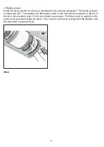
Page 8: ...scopic flue To assemble the filtering flue refer to the instructions contained in the kit If the kit is not provided order it from your dealer as accessory The filters must be applied to the suction unit positioned inside the hood They must be centred by turning them 90 degrees until the stop catch is tripped Fig 8 FIG 8 ...

Page 9: ...9 ...

Page 10: ...nium filters need cleaning every 14 hours operated Touch Control When the hood is initially switched on the Filter Clean symbol will illuminate To clear press the light symbol twice Light Button Used to switch the lights on and off With the lights switched on press and hold the light symbol to view the current filter time elapsed of the 14 hours before the filters need cleaning Timer Button To set...

Page 11: ...hing you can use the symbols to set any time between 1 and 99 minutes Once the timer symbol stops fla shing the timed operation will begin Once the timed operation is set the clock will then count down and switch off the fan lights once the time has elapsed An alarm symbol will illuminate and an audible alarm will sound for a few seconds To cancel the timed operation press and hold the symbol at a...

Page 12: ...ch off the electricity supply To avoid any fire risk the following cleaning instructions must be followed Grease Filters The grease filters absorb grease and dust from cooking fumes which would otherwise damage the inside of the hood The grease filters should be removed and cleaned regularly with normal use this should be every 2 months To clean use warm soapy water or wash in a dishwasher The gre...

Page 13: ...dBA Position 1 49 dB Light Bulbs 2 x 1 5W LED Motor Rating 203W Grease Filters 2 Off Aluminium panel Note After cleaning grease filters may lose their colour slightly this does not affect their perfor mance Carbon Filters 2 Off Available as Spares Extraction Rate External Booster 582 6 m3 H Position 3 582 6 m3 H Position 1 411 3 m3 H ...

Page 14: ...ear a recorded message and be given a number of options This indicates that your call has been accepted and is being held in a queue Calls are answered in strict rotation as our Customer Care Representatives become available Enter appliance numbers here for future reference These numbers can be found on your appliances Outside the UK and Northern Ireland refer to your local supplier Stoney Lane Pr...

Reviews: