Engineering Manual for
AXS Series S60 Keypads
S60 Engineering Manual
Page 5 of 12
Rev 1.6 May 2016
© Copyright Storm Interface. 2016. All rights reserved
Installation
-
Mark and drill the cable hole. Remove the release liner and stick the rear plate to the wall.
-
Fix the rear plate to the wall with the 2 x self drill countersink 25mm screws (on 150mm centres) , and feed through the cable
-
Strip the cable ends |
34
mm
| |
6
mm
|
-
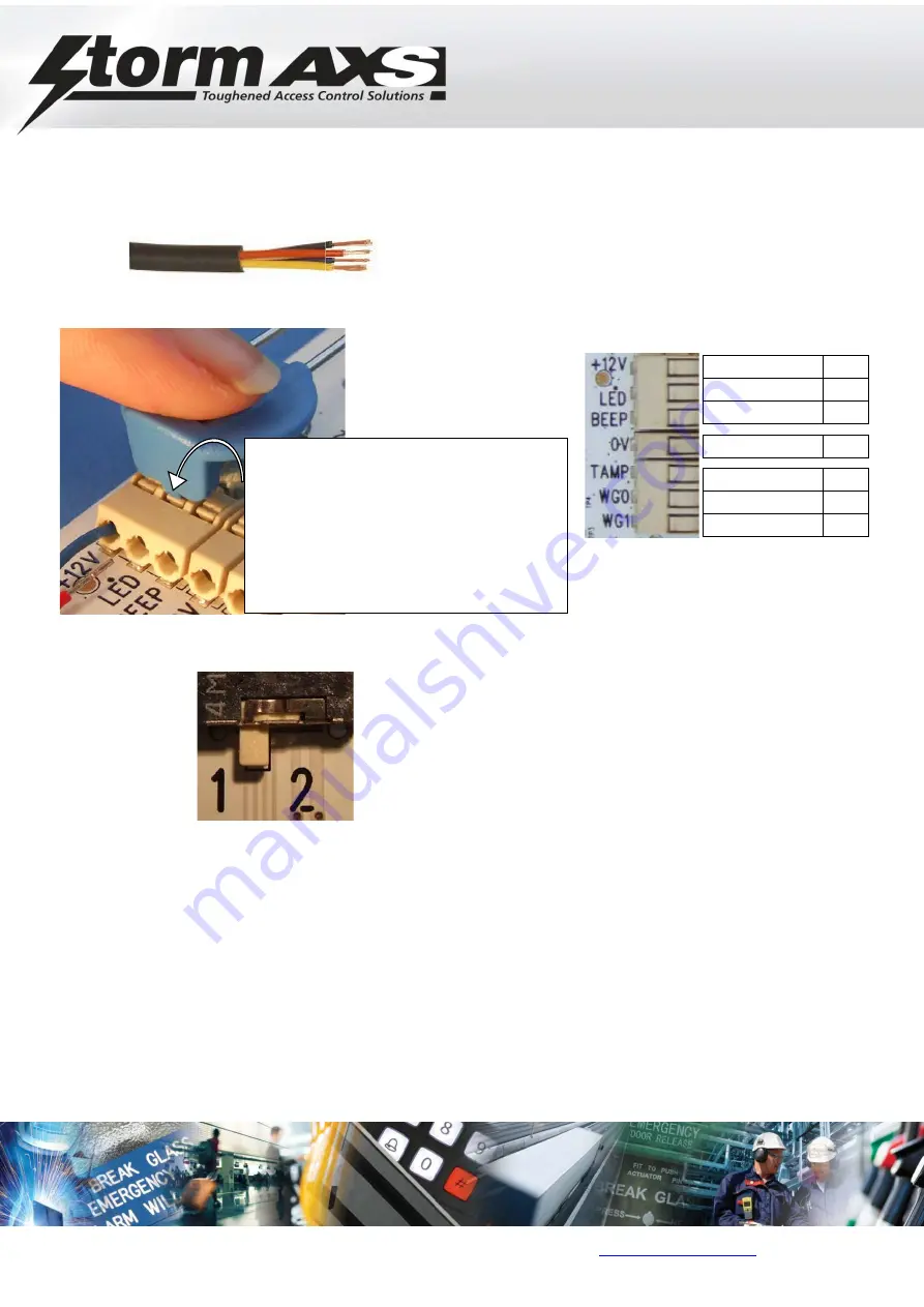
Make the wiring connections to the keypad.
-
Set the rear halo illumination switch SW13 to either ON (1) , OFF (2) (factory default shown is Position 1 : ON )
-
Fit the keypad to the rear plate : locate at top and then push at the bottom to engage clip
-
Recommended locations and wiring methods shall be in accordance with the National Electrical Code, ANSI/NFPA 70.
Use shielded cable
CONNECTIONS
+12 V
LED
BEEPER
0 V
TAMPER
WG0
WG1
USE 18-24AWG SOLID OR STRANDED
WIRE
STRIP WIRE TO 6MM BARE ENDS
PRESS DOWN ON CONNECTOR AS
SHOWN USING RELEASE TOOL
THEN PUSH IN WIRE
THEN RELEASE CONNECTOR TO
CLAMP WIRE


