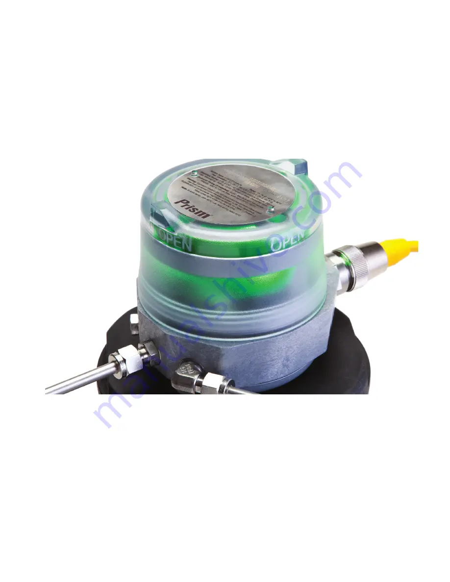
Prism™ PI
by StoneL
Installation, Maintenance and
Operating instructions
7 PI 70 en • 01/2021
StoneL publication 105431revC
Page 1: ...Prism PIby StoneL Installation Maintenance and Operating instructions 7 PI 70 en 01 2021 StoneL publication 105431revC...
Page 2: ...nting 7 2 1 Instructions 7 2 2 Prism PI assembly figure 8 3 Maintenance repair and installation 9 3 1 Maintenance and repair 9 3 2 Installation 9 3 3 Special conditions of use 9 4 Function specific de...
Page 3: ...this manual cannot cover all the likely situations that may occur when installing using or servicing the Prism PI If you are uncertain about the use of this device or its suitability for your intended...
Page 4: ...emoval clearance 84 1 mm 3 31 in 25 mm 1 in Standard stroke with visual indicator Unit height Cover removal clearance 107 9 mm 4 01 in 25 mm 1 in Long stroke Unit height Cover removal clearance 163 3...
Page 5: ...Flow rating Operating temperature Filtration requirements 120 VAC 50 60 Hz 1 0 watt 0 2 Cv Kv 0 17 based on flow m3 hr 10 C to 50 C 14 F to 122 F 40 microns 1N 33_ Operating voltage Power consumption...
Page 6: ...d under the download tab at www stonel com en products valve communication prism pi 1 or 2 1 2 NPT or M20 1 8 NPT 3 E P A 1 14 in 28 9 mm 0 39 in 9 9 mm Part of mounting system no visual indicator 3 3...
Page 7: ...ired Prism PI body can be rotated on the mounting plate in 45 increments Tighten the two body screws Item D with a M3 allen wrench to approximately 25 30 in lbs 2 8 3 4Nm 6 Back out the trigger assemb...
Page 8: ...sm PI assembly figure A Prism unit B Cover C Sensing module D Body screws 2 E Trigger assembly adjustment screw F Trigger assembly G Trigger shaft H Mounting plate fasteners I Unit O ring J Mounting p...
Page 9: ...to tighten the cover Attention If the unit is used in a manner not specified by StoneL the protection provided by it may be impaired WARNING Solenoid power supplied must be limited with a fuse or circ...
Page 10: ...ing only one of the sensors for valve position feedback the closed sensor red must be used Expanded dead band setting feature The Prism PI sensing module has the capability of changing the dead band o...
Page 11: ...rforming this procedure will cause the sensor inputs to change states Performing this procedure is not recommended during a live process Wiring diagrams Set Open push button Set Closed push button LED...
Page 12: ...sensor 45S continued Barrier off state target off current in NAMUR sensor circuit 2 1 mA Barrier on state target on current in NAMUR sensor circuit 1 0 mA power source Hazardous area NAMUR repeater ba...
Page 13: ...nctionality Wireless functionality allows remote monitoring position control and TEACH capabilities See page 22 for Wireless Link user guide WARNING Do not apply external power to the primary or secon...
Page 14: ...ediate control range 20 80 of valve stroke Intermediate control accuracy 3 of valve stroke Position feedback accuracy 1 of valve stroke Maximum resistance load Control Feedback 425 ohms 24 VDC 730 ohm...
Page 15: ...22 for Wireless Link user guide WARNING Do not apply external power to the primary or secondary solenoid terminals This will cause permanent damage to the unit Calibration The VDC IN terminals must be...
Page 16: ...mA 11 VDC Current consumption coil energized 66 mA 24 VDC 0 5 w coil 1N 83 mA 24 VDC 0 9 w coil 1K Maximum output current 167 mA all outputs combined Default address 63 software assigned Default baud...
Page 17: ...ature The unit must be addressed and correctly configured to be recognized by the control system 2 Set byte 0 bit 2 to 1 in the desired unit Once the correct unit has been physically located on the ne...
Page 18: ...ed Outputs Bit 0 set closed Bit 1 set open Bit 2 SOL OUT Bit 3 wink Specifications unique to 96W Bit assignment Inputs Bit 0 red LED valve closed Bit 1 green LED valve open Bit 2 not used Bit 3 not us...
Page 19: ...as been physically located on the network indicated by the winking of the CLOSED and OPEN LEDs set parameter Bit 0 back to 0 Performing this function will not change the Closed and Open sensor setpoin...
Page 20: ...2 3 4 FEMALE SOCKETS 2 1 3 4 Specifications Communication protocol AS Interface v3 0 Configuration 2 Discrete Inputs sensors 1 Discrete Output solenoid Input voltage 26 5 31 6 VDC AS I voltage Output...
Page 21: ...ve process Power Fault LED status AS i status LED Fault description LED off Device does not have power Solid green Normal operation Flashing red green Output shorted Flashing red green No magnet detec...
Page 22: ...le 2 The device list export allows you to export valve tag number device address baud rate if applicable valve actuator description valve position stroke time cycle count data and additional informati...
Page 23: ...implement changes made to the device address and or device baud rate Changing the device tag or address on an ASi unit 1 To change the tag edit the existing tag in the associated text field Item M Th...
Page 24: ...e and Operating Instructions located on the bottom buttons of the More Information screen require an internet connection to access Item C Image 4c Expeditor detail O P Q 5 4 Device detail screen conti...
Page 25: ...em G will erase the cycle count and start counting again from 0 3 The current temperature of the valve monitor is displayed along with the temperature range of the valve since last reset Item F Select...
Page 26: ...adiate radio frequency energy and if not installed and used in accordance with the instruction manual may cause harmful interference to radio communications Operation of this equipment in a residentia...
Page 27: ...AI and 2 24V DI for position feedback with Wireless Link PNEUMATIC VALVE TEMPERATURE 20 C to 60 C 0 1 Cv 10 C to 50 C 0 2 Cv 11S No pneumatic valve 1KS Three way 24 VDC 1NS Three way voltage power de...
Page 28: ...2011 Ex ia IIC T5 Ga Ex ia IIIC T100 C Da PI Series EMC 2014 30 EU LVD 2014 35 EU EN 60947 5 2 2007 A1 2012 EN 62026 2 2013 EN 62026 3 2009 EN 61000 6 2 2005 EN 61000 6 4 2005 EN 61326 1 2013 RED 201...
Page 29: ...ent that maintains the Prism enclosure rating Warning Substitution of components may impair intrinsic safety or suitability for Division 2 Keep cover tight while circuits are alive NOTE See also Contr...
Page 30: ...apparatus ground 8 Conduit Grounding Upon installation verify electrical continuity between conduit and ground terminal 9 Resistance between Intrinsic Safe Ground and earth ground must be less than o...
Page 31: ...noid coil wiring must be run in separate cables or separate shields connected to intrinsically safe associated apparatus ground 8 Conduit Grounding Upon installation verify electrical continuity betwe...
Page 32: ...56537 USA Tel 1 218 739 5774 stonel com Subject to change without prior notice Neles Jamesbury and Easyflow by Neles StoneL and certain other trademarks are either registered trademarks or trademarks...