Stoelting Futura 112 Owner'S Manual Download Page 17

7

SECTION 3

INITIAL SETUP AND OPERATION

3.1 OPERATOR'S SAFETY PRECAUTIONS

SAFE OPERATION IS NO ACCIDENT; Observe these
rules:

A.

Know the freezer. 

Read and understand the

Operating Instructions.

B.

Notice all warning labels on the freezer.

C.

Wear proper clothing. 

Avoid loose fitting gar-

ments, and remove watches, rings or jewelry which
could cause a serious accident.

D.

Maintain a clean work area.

 Avoid accidents by

cleaning up the area and keeping it clean.

E.

Stay alert at all times. 

Know which switch, push

button or control you are about to use and what
effect it is going to have.

F.

Disconnect electrical cord for maintenance.

Never attempt to repair or perform maintenance on
the freezer until the main electrical power has been
disconnected.

G.

Do not operate under unsafe operating condi-
tions.

 Never operate the freezer if unusual or exces-

sive noise or vibration occurs.

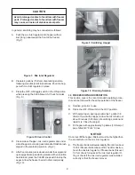
3.2 OPERATING CONTROLS AND INDICATORS

Before operating the freezer, it is required that the
operator know the function of each operating control.
Refer to Figure 6 for the location of the operating
controls on the freezer. For the information regarding
flashing indicator lights, refer to the troubleshooting
section.


WARNING

Hazardous voltage

The OFF-ON switch must be placed in the OFF
position when disassembling for cleaning or servicing.
The freezer must be disconnected from electrical
supply before removing any access panel. Failure to
disconnect power before servicing could result in death
or serious injury.

Figure 6.  Controls

High Pressure Cutout Switch Located Back of Freezer  (Some Models)

OFF-ON

POWER SWITCH

HOLD READY

SWITCH

PUSH TO FREEZE

CLEAN

MIX LOW

CONSISTENCY/TEMPERATURE
ADJUSTMENT

DISPENSE RATE

ADJUSTMENT

Î

Î

Î

Î

Î

Î

Î

Î

Î

Î

Î

Î

Î

Î

Î

Ô

Ô

Ô

Ô

Ô

Ï

Ï

Ï

Ï

Ï

Ð

Ð

Ð

Ð

Ð

Ó

Ó

Ó

Ó

Ó

Summary of Contents for Futura 112

Page 1: ...OPTIMA 112 OWNER S MANUAL Manual No 513602 Sept 2003 Rev 1...

Page 2: ......

Page 3: ...are certified in the Stoelting Technicare program Model No _______________________ Serial No _______________________ Purchase Date ____________________ Start Up Date ____________________ CALL Distrib...

Page 4: ......

Page 5: ...illustrations and specifications are not binding in detail We reserve the right to make changes to the freezer without notice and without incurring any obligation to modify or provide new parts for f...

Page 6: ......

Page 7: ...d Indicators 7 3 3 Sanitizing 8 3 4 Freeze Down and Operation 9 3 5 MixInformation 10 3 6 Removing Mix From Freezer 10 3 7 Cleaning The Freezer 11 3 8 Disassembly of Freezer Parts 11 3 9 Cleaning The...

Page 8: ...5 7 InstallingTrayandCover 5 8 PowerCordConnection 5 9 Controls 7 10 Mix Inlet Regulator 9 11 CleanControl 9 12 SanitizingHopper 9 13 DrainingSolution 9 14 DispensingProduct 10 15 RemovingMixInletReg...

Page 9: ...hlight specific safety information the following safety definitions are provided to assist the reader The purpose of safety symbols is to attract your attention to possible dangers The safety symbols...

Page 10: ......

Page 11: ...with fully automatic con trols to provide a uniform product The freezer is designed to operate with almost any type of commercial shake mix available This manual is designed to assist qualified ser vi...

Page 12: ...3 3kg ELECTRICAL Description Optima 112 38 Voltage AC 1 PH 208 230 Total Run Amps 10 5 Drive Motor 3 4 HP Compressor 12 000 BTUH 90 F 0 F Use 20 amp HACR circuit breaker Automatic safeguard circuit bu...

Page 13: ...n a safe working environment Thelabelshavebeendesignedtowithstand washing and cleaning All labels must remain legible for the life of the freezer Labels should be checked periodi cally to be sure they...

Page 14: ...klift lift table or pallet jack with lifting device positioned beneath the freezer s base Ensure that personnel remain clear of suspended load Failure to do so may result in personal injury and or dam...

Page 15: ...vethepowercord D Install permanent wiring according to local code E Replace the electrical box cover and left side panel WARNING Do not alter or deform electrical plug in any way Alteringtheplugtofiti...

Page 16: ...6...

Page 17: ...d G Do not operate under unsafe operating condi tions Never operate the freezer if unusual or exces sive noise or vibration occurs 3 2OPERATINGCONTROLSANDINDICATORS Before operating the freezer it is...

Page 18: ...xit the CLEAN mode turn the OFF ON switch to the OFF position If the freezer is left in CLEAN for more than 30 minutes or is pushed three times in ten seconds it will go in error To reset place the CL...

Page 19: ...oximately 5 gallons 19 liters of pre chilled 40 F or 4 C mix NOTICE Donotoverfillthehopper Mixlevelmustnotbehigherthan the air inlet tube on the mix inlet regulator E The freezer barrel will automatic...

Page 20: ...x in the hopper with a sanitized utensil 3 6 REMOVINGMIXFROMFREEZER To remove the mix from the freezer refer to the following steps A Remove the mix inlet regulator from the hopper by pulling straight...

Page 21: ...ately5minutes NOTICE If freezer is left in CLEAN for more than 30 minutes it will go to error D Openthespigottodrainthewater Remembertoplace a bucket or container under the spigot to catch the water W...

Page 22: ...e manufacturer s instructions Figure 17 Cleaning Freezer Barrel E Removetheaugerassemblyfromthefreezer Fig 15 Keep the rear of the auger shaft tipped up once it is clear of the freezer to avoid droppi...

Page 23: ...edriveshaft F Install the auger support bushing into the front door G Install the spigot body with O rings into the front door from bottom Push straight up until the spigot is in place H Install the f...

Page 24: ...d in a deliming solution for an extended period of time more about delimers in Additional Information It is recommended that a maintenance schedule be fol lowed to keep the freezer clean and operating...

Page 25: ...bility to remove milkstone Milkstone will become a problem if not remedied with additional products and procedures THE USE OF CHLORINE TEST STRIPS Test strips are used to determine concentrations of a...

Page 26: ...sconnect before cleaning or servicing Do not operate machine with cabinet panels removed 1 Check drive belt for proper tension Push belt in with one finger belt should deflect about 3 8 CAUTION Do not...

Page 27: ...n o i t a r e g i r f e R 5 e c i v r e s r o f r o t u b i r t s i d l l a C t s u j d a e R 1 e c i v r e s r o f r o t u b i r t s i d l l a C 2 e c i v r e s r o f r o t u b i r t s i d l l a C 3...

Page 28: ...n i r O r o t a l u g e r t e l n i x i M 2 e b u t r i a r o t a l u g e r t e l n i x i M 3 d e k c o l b n w o d k a e r b t c u d o r P 4 r o t a l u g e r t e l n i x i m e c a l p e R 1 g n i r...

Page 29: ...E R R E R R E R R E R R E R R E R R E To Clear Error Modes Clean Error 04 Allow freezer to remain on light blinking with the power switch in the ON position for ten 10 minutes minimum Next place the p...

Page 30: ...e r i u q e r s t i n u E M U L O V R E P P O H s r e t i l 2 8 1 3 t r a u Q 8 2 E M U L O V L E R R A B s r e t i l 7 5 7 t r a u Q 8 Y T I C A P A C G N I Z E E R F F 0 7 r u o h r e p s n o l l a...

Page 31: ...NG PN QTY DESCRIPTION 1 336530 SV 1 Front Door Shake 2 625314 1 O ring 6 OD x 1 4 CS 3 1 Door Pin 4 3177738 1 Spigot Body 5 624614 2 O ring 3 4 IDX 1 0 ODX 1 8 CS 6 508135 001 Lubricant Petro Gel 4 Oz...

Page 32: ...RIPTION 1 4177749 1 Auger Shaft 2 666786 1 Seal Rear with Insert 3 624678 1 O ring 1 1 2 x 1 1 8 x 3 16 CS 4 149002 1 Bearing Front Auger Celcon 5 508048 001 Spline Lubricant 6 508135 001 Lubricant Pe...

Page 33: ...es are subject to the conditions that Buyer a signs and returns to Stoelting upon installation the Checklist Warranty Registration Card for the affected equipment b gives Stoelting prompt written noti...

Page 34: ......

Reviews: