background image

Deselecting and requesting the safety function

ID 442181.07

16

Operating manual ASP 5001

5

WE KEEP THINGS MOVING

5

Deselecting and requesting the safety 

function 

In this section, you will find out how to deselect and request the safety function.
Deselecting a safety function means the safe state is left and regular operation of the drive is allowed. 
Requesting a safety function means that regular operation is left and the inverter is brought to the safe state.

5.1

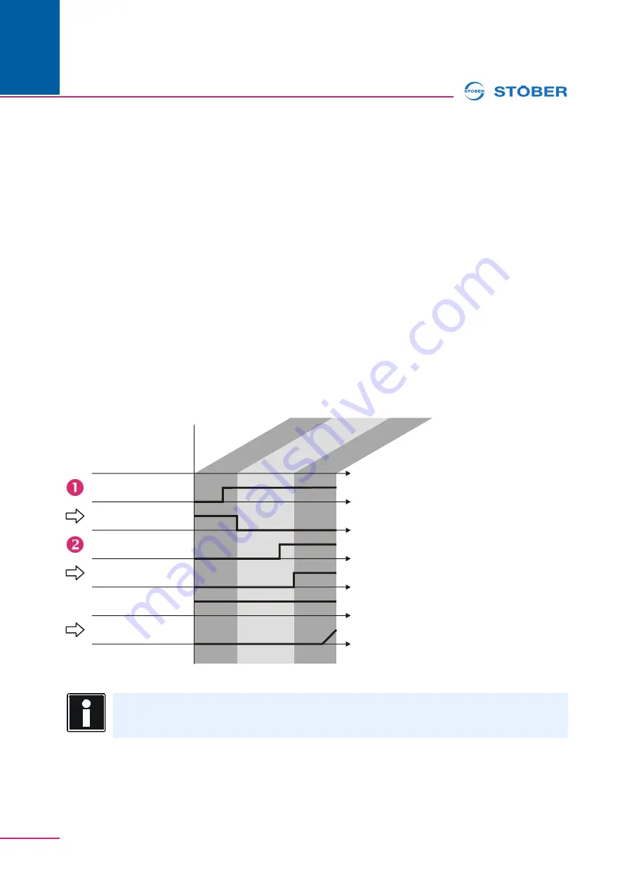
Deselect STO

Deselect STO

1. Switch on the signal at terminal X12.3/4.

The NC contact at terminal X12.1/2 is opened.

2. Turn on the controller enable.

The feedback system confirms the enable.

You have deselected the STO safety function.

Device state
(

)

E48

1:S

wit

cho

n d

isa

ble

2:R

ea

dy 

to s

wit

ch 

on

4:E

na

ble

d

Terminal X12.3/4
(Relay coil)

Terminal X12.1/2
(NC contact)

Enable

Response message
Control unit (

)

A900

Reference value

Actual value

STO

Information

To enable the power output stage, other signals may be required in addition to the controller 
enable, e.g.

Summary of Contents for ASP 5001

Page 1: ...ASP 5001 Operating manual Data Concept Example V 5 6 S or later 10 2017 en ...

Page 2: ...es on safety 9 3 Concept 10 3 1 1 Switchoff distance 11 3 1 1 Controller 11 3 1 2 Control commands and status information 11 3 2 2 Switchoff distance 12 3 3 Overall functionality 12 4 Data 13 4 1 1 Switchoff distance 13 4 2 ASP 5001 13 5 Deselecting and requesting the safety function 16 5 1 Deselect STO 16 5 2 Request STO 17 5 3 Request SS1 18 6 Sample application 19 6 1 Description 19 6 2 Calcula...

Page 3: ...Table of contents Operating manual ASP 5001 ID 442181 07 WE KEEP THINGS MOVING 3 7 xDS 5000 safety figures 23 7 1 PFH and MTTF 23 7 1 1 Size 0 to 2 23 7 1 2 Size 3 25 7 2 CCF 26 8 Glossary 27 ...

Page 4: ...ct is switched at the external safety circuit NC contact The start up of the motor is then also prevented when faults in the region of the power unit or the control circuit are present as the required rotating magnetic field is no longer generated Advantages of the start inhibitor No switching of the supply voltage required Faster restart possible Lower contact wear Simplified wiring The following...

Page 5: ...document versions at www stoeber de Manual Contents ID Commissioning Instructions MDS 5000 Reinstallation replacement function test 442297 Operating manual MDS 5000 Set up the inverter 442285 Manual Contents ID Commissioning Instructions FDS 5000 Reinstallation replacement function test 442293 Operating manual FDS 5000 Set up the inverter 442281 Manual Contents ID Commissioning Instructions SDS 50...

Page 6: ...e technical questions that are not answered by this document please contact Phone 49 7231 582 3060 E mail applications stoeber de If you have questions about the documentation please contact E mail electronics stoeber de If you have questions about training sessions please contact E mail training stoeber de ...

Page 7: ... situations The accessory ensures that the rotary field is switched off Secure vertically moving axles against falling Note that controlling the Safe Torque Off safety function with OSSD signals can lead to unexpected machine behavior The inverter enable can not evaluate OSSD signals or tolerate them in the presetting Activate the OSSD tolerance of the interface by entering a delay corresponding t...

Page 8: ...e despite an activated safety function in the event of a short circuit of two power transistors Example 4 pole motor maximum residual movement 180 2 90 Consider this residual movement for the risk analysis The motor coasts if the safety function is activated for a running motor Controlled stopping is no longer possible Consider this when configuring your system Activity Possible occupational quali...

Page 9: ...hat minor injury may occur if the stated precautionary measures are not taken WARNING Warning means that there may be a serious danger of death if the stated precautionary measures are not taken DANGER Danger means that serious danger of death exists if the stated precautionary measures are not taken Information refers to important information about the product or serves to emphasize a section in ...

Page 10: ...ated in the inverter For a suitable external configuration the Safe Stop 1 SS1 safety function to DIN EN 61800 5 2 2008 04 or a category 1 stop to DIN EN 60204 1 2007 06 can be realized In this way STO constitutes a safe fallback solution The devices from the 5th generation of STÖBER inverters meet the requirements for category 3 and HF1 configurations Accordingly the device has two switchoff dist...

Page 11: ...tional enable is always effective 3 1 2 Control commands and status information The 1st switchoff distance is acknowledged by the A900 SysEnableOutput signal via a binary output or fieldbus The signal must be dynamically checked by the higher level controller i e for a change in state For example the A900 coordinate is entered in the F61 parameter for the output on BA1 If the acknowledgement is vi...

Page 12: ...ety function is requested 3 3 Overall functionality Note that the following parameters can affect the safety function A39 Tmax Fast Stop A43 Enable Switchoff Delay A44 Enable Quick Stop A55 Manual Function Button A60 Additional Enable Source The F61 BA1 Source to F70 BA10 Source parameters Observe these when configuring commissioning and modifying your project Make sure that the setting of the par...

Page 13: ...ion X12 Terminal description X1 Pin Designation Function Data 3 GND Enable High level 12 V High level 8 V IE max 16 mA UE max 30 V 4 input Safety relevant data of the enable path Acknowledgement MTTFD DCavg Mission Time Without feedback system 377 years 60 20 years With feedback system 377 years 90 20 years Pin Id Function 1 NC contact break contact element Feedback system must be integrated in th...

Page 14: ...ng current 10 mA Maximum switching current 300 mA Maximum switching frequency 0 1 Hz Information The feedback contact must be monitored by the higher level safety controller Minimum service life of relay Utilization category Current Switching cycles DC 12 300 mA 450000 DC 13 300 mA 250000 Utilization category Current B10D value DC 13 1 A Size 0 size 2 10000000 cycles Size 3 7000000 cycles Informat...

Page 15: ...15 4 Maximum conductor cross section Connection type Maximum conductor cross section mm2 Rigid 1 5 Flexible 1 5 Flexible with cable end without plastic sleeve 1 5 Flexible with cable end with plastic sleeve 0 5 2 leads with the same cross section with double cable end ...

Page 16: ...on is left and the inverter is brought to the safe state 5 1 Deselect STO Deselect STO 1 Switch on the signal at terminal X12 3 4 The NC contact at terminal X12 1 2 is opened 2 Turn on the controller enable The feedback system confirms the enable You have deselected the STO safety function Device state E48 1 Switchon disable 2 Ready to switch on 4 Enabled Terminal X12 3 4 Relay coil Terminal X12 1...

Page 17: ... the signal at terminal X12 3 4 and the controller enable The NC contact at terminal X12 1 2 is closed The acknowledgement is switched off You have requested the safety function Device state E48 4 Enabled 1 Switchon disable Terminal X12 3 4 Relay coil Enable Terminal X12 1 2 NC contact Response message Control unit A900 Reference value Actual value STO ...

Page 18: ...at the power unit is no longer enabled 2 Switch off the signal at terminal X12 3 4 The NC contact at terminal X12 1 2 is closed You have requested the safety function Device state E48 1 Switchon disable 2 Ready to switch on 4 Enabled 7 Quick stop Enable Response message Control unit A900 Terminal X12 3 4 Relay coil Terminal X12 1 2 NC contact Reference value Actual value STO tmax Information Note ...

Page 19: ...pattern is blocked in the control unit by switching the signal at this input to low level This occurs immediately for the STO safety function after requesting the safety function For the SS1 a stop ramp must be parameterized in the xDS 5000 so that the drive can be initially stopped in a controlled manner before the generation of the pulse pattern is blocked The control unit can respond to the saf...

Page 20: ...ability is specified by the manufacturer as PFH 2 31 10 9 1 h For both other SB 1 and SB 3 subsystems the failure probability PFH is calculated as follows In order to determine the failure probability for the overall safety function of the sensor to the actuator the PFH values of the individual subsystems are added at the end MTTFd SB 1 An exclusion of faults for the electrical contact is possible...

Page 21: ...ement signal from T1a in the feedback loop K1 DC 60 can only be assumed for fault coverage by the process DC 99 for the T1b safety relay results from the direct monitoring of the positively driven contact by K1 With feedback from T1a this results in a DCavg 91 9 average and 68 2 low without T1a feedback CCF The minimum requirements are met see section 7 2 Subsystem Calculation Failure probability ...

Page 22: ... is described in the relevant application example a failure probability of PFHd 3 04 10 8 h 1 is determined This also corresponds to a PL d or SIL 2 6 3 2 DC 90 for Ta1 The failure probability for the safety relevant part of the inverter with DC 90 for T1a was determined to be PFHd 2 61 10 9 h 1 This corresponds to a SIL 3 according to DIN EN 61800 5 2 considering the structural limitations of the...

Page 23: ...ears according to DIN EN ISO 13849 1 2008 12 100a 2 minutes 6 059 10 9 4 554 10 9 5 minutes 2 432 10 9 1 824 10 9 10 minutes 1 218 10 9 9 123 10 10 30 minutes 4 062 10 10 3 042 10 10 1 hour 2 032 10 10 1 521 10 10 2 hours 1 016 10 10 7 605 10 11 4 hours 5 080 10 11 3 803 10 11 8 hours 2 540 10 11 1 901 10 11 16 hours 1 270 10 11 9 506 10 12 1 day 8 467 10 12 6 338 10 12 2 days 4 234 10 12 3 169 10...

Page 24: ...10 9 5 minutes 3 644 10 9 2 735 10 9 10 minutes 1 825 10 9 1 368 10 9 30 minutes 6 092 10 10 4 562 10 10 1 hour 3 047 10 10 2 281 10 10 2 hours 1 524 10 10 1 141 10 10 4 hours 7 620 10 11 5 704 10 11 8 hours 3 810 10 11 2 852 10 11 16 hours 1 905 10 11 1 426 10 11 1 day 1 270 10 11 9 506 10 12 2 days 6 350 10 12 4 753 10 12 5 days 2 540 10 12 1 901 10 12 1 week 1 814 10 12 1 358 10 12 2 weeks 9 07...

Page 25: ... 6 501 10 9 5 minutes 3 471 10 9 2 605 10 9 10 minutes 1 739 10 9 1 303 10 9 30 minutes 5 803 10 10 4 345 10 10 1 hour 2 902 10 10 2 173 10 10 2 hours 1 451 10 10 1 086 10 10 4 hours 7 257 10 11 5 432 10 11 8 hours 3 629 10 11 2 716 10 11 16 hours 1 814 10 11 1 358 10 11 1 day 1 210 10 11 9 054 10 12 2 days 6 048 10 12 4 527 10 12 5 days 2 419 10 12 1 811 10 12 1 week 1 728 10 12 1 293 10 12 2 wee...

Page 26: ... h MTTFd years DC 60 DC 90 DC 60 DC 90 1 minute 1 480 10 8 8 434 10 9 100a a MTTFd is reduced to 100 years according to DIN EN ISO 13849 1 2008 12 100a 2 minutes 1 044 10 8 7 244 10 9 5 minutes 5 198 10 9 3 905 10 9 10 minutes 2 606 10 9 1 954 10 9 30 minutes 8 701 10 10 6 517 10 10 1 hour 4 353 10 10 3 259 10 10 2 hours 2 177 10 10 1 630 10 10 4 hours 1 088 10 10 8 148 10 11 8 hours 5 443 10 11 4...

Page 27: ...t based on a mutual cause DCavg average Diagnostic Coverage Specifies the average probability of revealing errors by a test MTTF MTTFd Mean Time To dangerous Failure Also mean service life Statistical parameter that is determined by trial and empirical values Does not specify a guaranteed service life or guaranteed fault free time PFH PFHd Probability of a dangerous Failure per Hour PL Performance...

Page 28: ...Notes WE KEEP THINGS MOVING ...

Page 29: ... Staffordshire WS12 2HA Fon 44 1543 458 858 sales stober co uk www stober co uk STOBER Turkey Istanbul Fon 90 212 338 8014 sales turkey stober com www stober com STÖBER SCHWEIZ AG Rugghölzli 2 5453 Remetschwil Fon 41 56 496 96 50 sales stoeber ch www stoeber ch STOBER S a r l 131 Chemin du Bac à Traille Les Portes du Rhône 69300 Caluire et Cuire Fon 33 4 78 98 91 80 sales stober fr www stober fr S...

Page 30: ... Co KG Kieselbronner Str 12 75177 PFORZHEIM GERMANY Fon 49 7231 582 0 mail stoeber de 24 h Service Hotline 49 7231 5823000 Technische Änderungen vorbehalten Errors and changes excepted ID 442181 07 10 2017 442181 07 www stober com ...

Reviews: