background image

WORKSHOP MANUAL

MPV 320W / 520W

Chapter

6 - CUTTING DECK AND COLLECTION 

EDITION

2017

PAGE

39 /

64


4.   In  different  values  are  detected,  loosen  the 

nut  (8)  and  turn  the  handle  (9)  screwing  or 

unscrewing it on the bolt (10) until the correct 

value is reached.

5.   When the adjustment has been made, tighten 

the nut (8).

 NOTE


If the correct value cannot be reached, it 

is necessary to adjust the spring (6) nut (4) again.

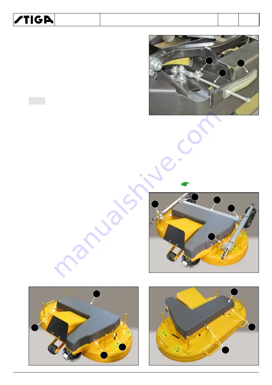
6.2.4   Replacing and adjusting the blade connection belt

•  Follow all steps of the "Removing the cutting deck” procedure 

[

 6.1.3]

.

1.   Release the four split pins (1) and remove the 

pivot arm carriage (2).

2.   Remove the protective cover (3) fixed by the 

five screws (4).

8

10

9

2

1

1

1

1

3

4

4

4

3

4

4

Summary of Contents for MPV 320 W

Page 1: ...MPV 320W MPV 520W 2017 2019 WORKSHOP MANUAL ...

Page 2: ...private individuals or inadequate facilities This manual does not contemplate interventions and repair work on the engine and transmission units as it is necessary to contact the Service Centres of the respective Manufacturers or obtain documentation sup plied by the same The manual has left out the simplest and quickest operations that can be handled by a good mechanic while concentrating more on...

Page 3: ...he manual is divided into chapters paragraphs and sub paragraphs The front inside cover provides the table of contents indicating the various chapters Each chapter is dedicated to a specific topic and is preceded by an index that marks the various paragraphs contained therein Each paragraph is further divided into sub paragraphs relative to a single procedure Cross references to other parts of the...

Page 4: ...nual followed by the number of the relevant chapter paragraph or sub paragraph b Safety terminology and notes Some paragraphs are preceded by a definition that highlights their importance NOTE General reference for the correct maintenance execution and methods IMPORTANT Specific procedures or information necessary to avoid damage to the machine or equipment WARNING Non observance will result in th...

Page 5: ...do not entail particularly hazardous situations besides the normal hazard related to mechanical operations and that can be avoided by taking the neces sary care and attention normally required for this type of work As well as following the usual accident prevention regulations that apply to most repair shops we recommended you remove the ignition key before beginning any repair work protect hands ...

Page 6: ...he engine which results in a change in performance or use that is incorrect or different from the purpose for which it was designed and approved warn the Customer that failure to comply with the above points automatically voids the warranty and the responsibility of the Manufacturer 1 3 SERVICE CENTRE PROCEDURES 1 3 1 Machine registration The Warranty registration card must be completed signed and...

Page 7: ...ced parts in case of any subsequent disputes with Customers 1 3 5 Fault notification The Manufacturer welcomes any notifications of faults that recur with particular frequency It gives the opportunity for a careful inspection of the problem and the implementation of corrective action at production level Similarly the Manufacturer will report any faults discovered on the machines produced with rec ...

Page 8: ... specifications which differentiate it from similar items by this same Manufacturer The engine has a serial number that clearly identifies the product and its specifications this number must al ways be quoted when requesting spare parts or any information from the Manufacturer Summary 2 1 IDENTIFICATION OF THE MACHINE AND COMPONENTS 8 2 1 1 Machine identification 8 2 1 2 Engine identification 8 2 ...

Page 9: ...er 2 2 EQUIPMENT REQUIRED 2 2 1 Basic equipment All the operations can be carried out with the tools normally available at any good car Servicing Centre The availability of an adequate lifting platform for the weight and dimensions of the machine makes it more practical to perform the interventions in the lower area of the machine 2 2 2 Special equipment No special tools or equipment are required ...

Page 10: ...Replace the split pin 5 to prevent the pin from accidentally sliding out 4 Lift it just enough to insert two stands 6 under the front part of the lon gitudinal sections 7 of the chassis Lower the lifting device and make sure the machine is stable be fore starting any work 2 3 3 Rear lifting Remove the cutting deck 6 1 3 Engage the parking brake to prevent any uncontrolled movement of the machine P...

Page 11: ...Cleaning the machine Clean the machine seat cutting deck etc removing all dirt and debris Do not use high pressure washers sol vents aggressive detergents or abrasive cleaners Re store damaged paint using STIGA paint Check and sharpen the cutting deck blades Check that the blades are not worn or damaged Sharpen and balance the blades 6 2 1 Check the tyre pressures See the technical specifications ...

Page 12: ...appropriate checks every time there is the chance to do so The machine safety system includes a Electric safety devices Always check the operation of the safety microswitches simulating various situations of use as indicated in the specific chapter 7 1 2 b Safety labels and symbolss These labels are considered an integral part of the safety devices Always replace illegible and missing labels as sh...

Page 13: ...38 kW 2400 1 11 66 kW 2400 1 Tank capacity litres 24 Electrical system Voltage 12 V Battery 44 Ah 420 CCA Transmission Transmission unit brand and model Hydro Gear G730 Transaxles Maximum forward speed km h 8 Maximum reverse speed km h 7 Control belts Gates Quad Power III XPA 1082 Gates Quad Power III XPA 690 Wheels and Tyres Front Tubeless 16 x 7 50 8 Rear Tubeless 13 x 5 6 Front tyre pressure kP...

Page 14: ...WORKSHOP MANUAL MPV 320W 520W Chapter 3 TECHNICAL DATA EDITION 2017 PAGE 14 64 3 2 OVERALL DIMENSIONS 1120 2530 1350 ...

Page 15: ...or an authorised Service Centre 4 1 2 Removal of the engine Remove the protective bar and the electromag netic clutch following steps 1 to 7 of the Re placement and adjustment of the lower belt procedure 5 1 2 1 Remove all engine connections the accelerator cable the choke cable the cabling connector the starter motor connector the earth cables 2 Remove the muffler 2 protection 1 secured by screws...

Page 16: ...engine must be replaced with a new one retain the accessories and fasteners that may not be included in the new engine supplied To reassemble follow the operations described above in the reverse order taking care to tighten the engine fastening screws to a torque of 23 27 Nm carefully reinstate all electric connections reconnect the fuel pipe making sure there are no leaks After reconnecting the c...

Page 17: ...n the tank connection pipe WARNING Be careful not to dis perse petrol in the work area and thor oughly clean up all traces of any spillage 5 Remove the clamp 8 from under the tank 9 and disconnect the petrol pipe 7 without re moving it completely 6 Undo the four screws 10 and remove the tank 9 To reassemble follow the operations described above in the reverse order taking care to replace all the c...

Page 18: ...g the upper belt 18 5 1 2 Replacing and adjusting the lower belt 19 5 1 3 Adjusting the neutral gear 22 5 1 4 Adjusting the parking brake 22 5 1 5 Adjusting the transmission cable 23 5 1 6 Transmission Unit maintenance 24 5 1 7 Removing the transmission unit 26 5 2 WHEELS AND TYRES 28 5 2 1 Removing and replacing the rear wheels 28 5 2 2 Replacing the front wheels 28 5 2 3 Replacing the rear wheel...

Page 19: ...the screws 4 Loosen and remove the belt 7 from the pul leys 5 Fit the new belt 7 following the diagram 6 Replace the head 6 and adjust the nut 8 un til the spring 9 is 80 mm long 5 1 2 Replacing and adjusting the lower belt The lower belt connects the engine to the return shaft For interventions follow the procedure below 1 Pull the lever 1 located near the right front wheel to loosen the cutting ...

Page 20: ...rd 5 fixed by the rear screw 6 by a screw on the right side 7 and a top screw 8 4 Remove the left rear guard 9 fixed by the nut 10 and by a screw 11 with nut positioned near the muffler 5 Remove the longitudinal protective bar 12 fixed at the back by one nut 13 and at the front by two nuts 14 10 9 11 14 14 12 12 13 6 7 8 ...

Page 21: ...e spring which causes a sudden movement of the head after loosening the screws 9 Loosen and remove the belt 23 from the pul leys 10 Fit the new belt 23 following the diagram 11 Replace the head 22 and adjust the nut 24 until the spring 25 is 60 mm long To reassemble follow the operations described above in the reverse order taking care to tighten the clutch fastening screws to a torque of 48 52 Nm...

Page 22: ...he accelerator to maximum speed 4 Check the axle rotation If the axle does not ro tate proceed to Step 5 If the axle does rotate proceed to Step 6 5 Stop the engine and reconnect the rod and ad just the mechanical linkage of the machine 6 Observe the direction of the axle rotation Switch the engine off Loosen the adjuster screw 2 so that it is possible to rotate the control arm 3 Rotate the contro...

Page 23: ...on it so that it opens and closes the contacts each time the lever is used 5 1 5 Adjusting the transmission cable NOTE The hydrostatic transmission unit has a predetermined range of use given by the sum of the maximum speeds in forward and reverse gear Therefore any increase of either of the two parameters reduces the other and vice versa Adjusting the cable makes it possible to pre determine the ...

Page 24: ...6c of the lever 6 In that case you may need to take action on the front register 8 to find the optimal conditions provided for in sections 2 and 4 NOTE If the pedal is not reacting properly check and or replace the gas spring which facilitates the return to neutral position of the pedal 5 1 6 Transmission Unit maintenance This transmission is provided with an external filter for ease of maintenanc...

Page 25: ...rom when the filter gasket makes contact with the surface of the filter base 5 Replace the filter cover 2 with three screws 1 tightened with a torque of 7 5 Nm 6 Remove the oil from the old filter before dis posal Collect the oil in appropriate containers and dispose of it in an approved recycling fa cility 7 Remove the oil level cap 4 before pouring in the oil to allow air to vent during filling ...

Page 26: ...achine drive wheels raised off the ground Then repeat the same operations under normal operating conditions If this is not feasible per form the procedure in an open area keeping a distance from objects or persons 1 Disengage the parking brake if engaged 2 With the bypass valve open and the engine running slowly move the drive pedal forward and backward 5 or 6 times 3 With the bypass valve closed ...

Page 27: ...ever by the pin 5 and the spring 6 5 The hydrostatic unit 7 is fastened to each side of the chassis by means of three screws 8 with relative 9 Carefully unscrew the low er nuts 9 adequately supporting the unit so it does not fall When reassembling perform the operations de scribed above in the reverse order Tighten the nuts 9 with a torque of 23 27 Nm When assembly is complete Check the parking br...

Page 28: ...ing hole WARNING ALWAYS replace deformed rims as they could impair the hold of the tyre On assembly it is advisable to spread grease on the shaft to facilitate the next wheel removal 5 2 2 Replacing the front wheels Lift the front part of the machine 2 3 2 The front wheel 1 is fixed by four screws 2 WARNING ALWAYS replace deformed rims as they could impair the hold of the tyre When replacing tight...

Page 29: ...TANT We recommend you always re place both hub bearings 5 2 4 Replacement and repair of tyres The tyres used on this machine are of the Tubeless type and so every repair of a hole in the tyre must be done by a tyre specialist according to the methods used for this type of tyre IMPORTANT The rear tires can have different rolling diameters due to wear or after replacement of one of the two These dif...

Page 30: ...and screw or unscrew the heads 4 on the rod until the indicated distance is achieved 3 Remount the rod and fully tighten the nuts 3 and lock nuts 5 5 3 2 Adjusting the drive direction This adjustment must be carried out if the machine tends to deviate its trajectory to the right or left with the steering wheel straight Check the toe in 5 3 1 Align the rear wheels 1 Unscrew the nut 1 and remove the...

Page 31: ...Final adjustment This setting determines the two steering stroke ends 3 Loosen the two screws 4 and 6 and the relative lock nuts 5 and 7 4 Turn the steering wheel to the right up to the limit determined by the screw 2 5 Tighten or loosen the corresponding screw 4 until leave 1 mm of light between the screw head and relative block point 8 then tighten the lock nut 5 6 Turn the steering wheel fully ...

Page 32: ...2017 PAGE 32 64 1 Loosen the four screws 1 2 Move the whole crown 3 support plate 2 forward or backward to eliminate any clear ance between the crown teeth and the pinion while maintaining a sufficient degree of fluid movement 3 Tighten the screws 1 to a torque of 23 27 Nm 1 2 3 ...

Page 33: ...ver 1 located near the right front wheel to loosen the cutting deck drive belt Summary 6 1 PREARRANGEMENT FOR ACCESSIBILITY 33 6 1 1 General information 33 6 1 2 Verticalisation of the cutting deck 33 6 1 3 Removal of the cutting deck 35 6 2 INTERVENTIONS ON THE CUTTING DECK 36 6 2 1 Removing sharpening and reassembling the blades 36 6 2 2 Blade control belt replacement 38 6 2 3 Adjusting the tens...

Page 34: ... sliding carriage and replace the rela tive split pins 7 5 Remove the two front split pins 11 from the left and right sides and remove the respective pins 12 to allow the carriage to slide on the guides 6 Align the two front wheels 7 Grasp the two handles 13 and pull the cutting deck 14 forwards as far as possible 8 Using the same handles move the cutting deck 14 into a vertical position WARNING S...

Page 35: ...h to allow the extraction of the cutting deck from the front Follow steps 1 to 2 of the Verticalisation of the cutting deck procedure 6 1 2 1 Release the two rear split pins 1 from the left and right sides and remove the respective pins 2 2 Rotate the levers 3 forwards to the right and to the left to unlock and disengage the respective pivot arms 4 from the forks 5 3 Grasp the cutting deck 6 using...

Page 36: ...ode 6 2 INTERVENTIONS ON THE CUTTING DECK 6 2 1 Removing sharpening and reassembling the blades WARNING Always wear protective gloves when handling the blades WARNING The blades are connected to each other the rotation of each blade en gages the rotation of the other Follow all steps of the Verticalisation of the cut ting deck 6 1 2 1 Unscrew the four nuts 1 and remove the plate 2 and the blade ho...

Page 37: ...eplace ment blades are supplied in pairs or are already assembled on the disc bear in mind that the unit and the right side blades are different from those of the left When assembling them repeat the operations described above in the reverse order taking care to Observe the blade assembly direction 6 on the disc with the tabs pointing toward the inside of the cutting deck and the cutting edge cons...

Page 38: ...order 6 2 3 Adjusting the tension of the blade control belt NOTE Make the adjustment with the cutting deck correctly assembled and in a fully lowered position 1 Remove the right side 1 fixed by a quick release fastener 2 and by a screw 3 2 Perform a preliminary adjustment by screw ing or unscrewing the nut 4 until it is brought to 1 mm from thread limit of the pin 5 corre sponding to a length of t...

Page 39: ...reached 5 When the adjustment has been made tighten the nut 8 NOTE If the correct value cannot be reached it is necessary to adjust the spring 6 nut 4 again 6 2 4 Replacing and adjusting the blade connection belt Follow all steps of the Removing the cutting deck procedure 6 1 3 1 Release the four split pins 1 and remove the pivot arm carriage 2 2 Remove the protective cover 3 fixed by the five scr...

Page 40: ...osen the toothed belt 12 6 Remove the belt 12 When reassembling perform the operations de scribed above in the reverse order IMPORTANT Replace the belt reinstating the tra jectory indicated in the diagram and making sure the blades are oriented at 90 to each other Replace the eccentric belt guide 6 leaving a 0 5 mm clearance between the belt and the sur face of the belt guide Before tightening the...

Page 41: ...utting deck WARNING Place the cutting deck so that both sides are accessible securing it so as to ensure stability and safety when working 1 Unscrew the four nuts 1 and remove the plate 2 and the blade holder disc 3 2 Unscrew the nut 4 and remove the entrain ment plate 5 together with the washer 6 be low 3 Undo the three screws 7 fastening each flanged support 8 to the cutting deck a Removal of th...

Page 42: ...screws 11 5 Unscrew the nut 12 and remove the lower pulley 13 and the washer 14 6 Locate and undo the three fixing screws and release the flange support from the drive pul ley When reassembling perform the operations de scribed above in the reverse order Tighten the nuts 1 with a torque of 23 27 Nm b Removal of the blade pulley supports 1 Unscrew the nut 1 and remove the toothed pulley 2 and the w...

Page 43: ...anged supports although some details are different require the same procedures for removing and replacing components To replace the drive shaft or bearings follow the procedure below 1 Remove the key 1 and hit the shaft with a plastic mallet on the toothed pulley side in or der to remove the shaft 2 together with the lower bearing 3 the spacer 4 and the dust guard disc 5 2 The upper bearing 6 stil...

Page 44: ...nary adjustment of the tie rods and lifting springs NOTE This adjustment is NOT included in the standard controls as it is set to default factory settings and requires no further adjustment The calibration of the tie rods and springs should only be performed if the relative components are re placed Follow the steps in the previous procedure inter vening alternately from both sides 1 Completely loo...

Page 45: ...comes into contact with the armature and the rotor NOTE This clutch uses 24UNF adjustment nuts therefore one turn of the nut is equivalent to about 1 mm of axial movement IMPORTANT During the adjustment bear in mind that the air gap with lower set values increases the period that elapses between one regula tion and another the gap set to a lower value reduces to a min imum the duration of the clut...

Page 46: ...rocedure 6 1 3 1 Unscrew the three nuts 1 fixing the rear of the collector 2 in place 2 Undo the three screws 3 located inside the outlet nozzle 3 Remove the conveyor 2 6 4 GRASS CATCHER 6 4 1 Removing the grass catcher Use the designated lever to raise the grass catcher and block it in the raised position 1 Extract the cotter pin 1 and remove the tilting system 3 connection pin 2 3 3 3 2 1 1 1 2 ...

Page 47: ... Extract the pin 4 from both sides using a suit ably sized pin punch 3 Extract the cotter pin 5 and remove the side catcher support connection pin 6 Take necessary measure to adequately support the catcher which may be subject to uncontrolled movements when disconnected from its supports 5 4 6 ...

Page 48: ... 2 7 Relay and Fuse operating faults 59 7 2 8 Diodes and Rectifiers 59 7 2 9 Electromagnetic clutch 60 7 3 FUNCTIONAL CHECKS 61 7 3 1 General system checks 61 7 3 2 Checking the components 61 7 4 ELECTRICAL WIRING DIAGRAMS 63 7 4 1 Wiring layout 63 7 ELECTRICAL SYSTEM PROBLEM CAUSE REMEDY Engine does not start The ignition consent conditions have not been complied with Comply with all consent cond...

Page 49: ... Disengaged OFF Off Disengaged OFF Machine ignition Engine does NOT start None Disengaged OFF Off Disengaged OFF Machine ignition with the drive pedal pressed Engine does NOT start None Disengaged OFF Off Engaged ON Machine ignition Engine does NOT start The engine ignition conditions are The blade engagement and grass cut ting conditions are Parking brake engaged Blades disengaged Grass catcher c...

Page 50: ...onnections and an assortment of automotive type wire in several colours IMPORTANT STIGA highly recommends that all interventions be performed in a professional manner The use of the tubing to cover joints and the soldering of connections contribute to a pro fessional looking job In addition to a pleasing appearance repairs made in this manner are more likely to withstand vibration The weakest poin...

Page 51: ...display Because of the internal circuitry and the lack of a movement these meters are not likely to be damaged by overloads In the discussions that follow either type of meter may be used Test procedures are the same It is best to learn proper procedures even though some meters may be more forgiving of mistakes Where differences in use may occur they will be covered in the explanations 7 1 5 Elect...

Page 52: ... that conducts current 7 2 SYSTEM AND COMPONENT DESCRIPTIONS 7 2 1 Wiring The diagram shows the cabling layout and the arrangement of the utilities 1 General wiring 2 Fuse box and relays 3 Battery 4 Ignition unit 5 Headlight switch 6 PTO switch 7 Starter relay 8 Operator presence microswitch 9 Parking brake microswitch 10 Grass catcher tilting microswitch 11 Upper casing microswitch 12 Left bonnet...

Page 53: ...he battery and its terminals clean Re place the battery if damaged Clean or service the battery after removing it from the machine Remove corrosion from battery terminals and cable connections with a wire brush then wash with a weak baking soda solution Scrub the exterior of the battery and cable terminals with a nonmetallic brush which has been dipped into a mixture of baking soda and water After...

Page 54: ...ttery of similar or higher CCA 3 1 f Emergency jump start with cables Jump starting battery charging or replacement is required when the starter motor will not crank the engine IMPORTANT The machine used for jump starting should have a 12 volt battery with at least 500 cold cranking amperes and a negatively grounded system DANGER FROZEN BATTERIES CAN EXPLODE and result in death or serious in jury ...

Page 55: ...pping current flow through it An example is an ignition switch that grounds the mag neto when in the OFF position completing the circuit but opens the circuit when in the ON po sition allowing the engine to operate The switches are selected with reference to their nominal current the contacts must be of sufficient size to carry the required current rated voltage and type of actuation pressure swit...

Page 56: ... electrical components in different situations NOTE The continuous line indicates the electrical continuity of the circuit All switches are shown from the rear The normally closed switch contacts are marked with NC normally open contacts do not have a mark 50 87 86 30 85 87A 87 86 30 85 87A 1 2 1 2 30 15 54 50 30 15 54 50 30 15 54 BK 1 2 1 2 21 22 13 14 21 22 13 14 PTO Switch Operator presence swi...

Page 57: ...ty through a coil of wire will create a magnetic field strong enough to attract a piece of iron or steel Each device uses this principle in a slightly different man ner Solenoids A basic solenoid consists of a coil of wire wound around a hollow tube A magnetic core slides inside the tube When current is passed through the coil the core is pulled into the solenoid with considerable force With prope...

Page 58: ...s in the start circuit If the voltage is correct turn off the power and check continuity of the coil with an ohmmeter If the coil is open the solenoid is faulty and must be replaced If the coil has the proper voltage applied and the continuity check indicates the coil is intact the solenoid plunger is stuck or the contacts are welded shut and the solenoid must be replaced If the solenoid snaps shu...

Page 59: ... to contact 87A the engine will start with PTO ON R2 PTO safety switch relay If contact 30 remains stuck to contact 87 the PTO is always ON If contact 30 remains stuck to contact 87A the PTO does not work and if engaged it switches OFF the engine R3 Ignition consent relay from safety switches If contact 30 remains stuck to contact 87 the engine will not start If contact 30 remains stuck to contact...

Page 60: ... may also contain a regulator to prevent overcharging the battery NOTE The repair of rectifiers integrated in the engine must be performed by a service centre authorised by the engine manufacturer which has access to the information and parts needed for the checks and repairs 7 2 9 Electromagnetic clutch The electromagnetic clutch is used to connect or disconnect via a switch the equipment used on...

Page 61: ...check if the battery voltage is transferred from ter minal 30 to terminal 15 54 Phase 4 With the ignition switch in the START position the battery voltage is transferred from terminal S2 to supply terminal of the contractor R8 Checking the clutch of the PTO Remove the clutch connectors Check the coil resistance of the clutch with a multimeter to see if the coil is working fine The clutch needs to ...

Page 62: ...ntacts Test for transfer of power with a voltmeter The switch contacts should be tested using an ohmmeter after discon necting the wiring connector Diode test The diodes are tested with an ohmmeter set to diode testing Voltage must travel in one direction only If voltage travels in both directions or there is no voltage at all the diode is faulty and must be replaced ...

Page 63: ...de microswitch N2 Brake alarm stop microswitch O Grass catcher closed microswitch P Operator presence microswitch Q Diode suppressor on PTO switch R Parking brake microswitch R8 Ignition Contactor S System earthing T Hour counter U Battery V Diode suppressor on blade clutch Y PTO fuse Z System protection fuse M1 R1 Ignition consent relay from PTO M1 R2 PTO safety switch relay M1 R3 Ignition consen...

Page 64: ...GGP Italy S p A Via del Lavoro 6 31033 Castelfranco Veneto TV Italy www stiga com ...

Reviews: