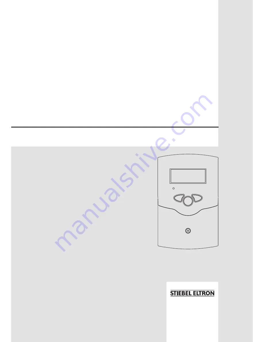
OperatiON aNd iNstallatiON
sOlar CONtrOller
» sOM 6 plus
Page 1: ...OperatiON and installation Solar ControLler SOM 6 plus ...
Page 2: ...a warning triangle Î Î They contain information on how to avoid the danger described Note Notes are indicated with an information symbol Subject to technical change Errors excepted Please pay attention to the following safety advice in order to avoid danger and damage to people and property Instructions Attention should be paid to Valid national and local standards and regulations Respective valid...
Page 3: ...ata Housing plastic PC ABS and PMMA Protection type IP 20 EN 60529 Ambient temp 32 104 F 0 40 C Size 6 8 4 3 1 9 172 110 47 mm Mounting wall mounting mounting into patch panels is possible Display System screen for system visualization 16 segment display 7 segment display 8 symbols for system status and operating control lamp Operation by 3 push buttons at the front of the housing Functions Differ...
Page 4: ...see chap 1 2 Electrical connection Î Î Place the cover back onto the housing Î Î Fasten the cover by means of the cross head screw 1 Installation 104 mm 4 1 130 mm 5 1 upper fastening lower fastening VBus 1 2 Electrical connection power supply terminals fuse load terminals sensor terminal ground terminal Note The minimum pump speed must be set to 100 when auxiliary relays or valves are connected W...
Page 5: ... terminal The temperature sensors S1 up to S4 are to be connected to the following terminals with either polarity 1 2 Sensor 1 e g Sensor collector 3 4 Sensor 2 e g Sensor tank 5 6 Sensor 3 e g Sensor tank top 7 8 Sensor 4 e g Sensor return All Pt1000 temperature sensors are equipped with a platinum measuring element in their tip The electrical resistance of the measuring element changes in relati...
Page 6: ...s Channel Description Terminal Page INIT x ODB initialization active 12 FLL x ODB filling time active 12 STAB x ODB stabilization in progress 12 COL x Temperature collector S1 12 TST x Temperature tank S2 12 S3 x Temperature sensor 3 S3 12 S4 x Temperature sensor 4 S4 12 TR x Temperature return sensor S4 12 n x Pump speed R1 R1 13 hP x Operating hours R1 R1 13 kWh x Heat quantity kWh 13 MWh x Heat...
Page 7: ...FF 16 DTCO x Cooling switch on temperature difference 40 0 Ra 20 0 K 16 DTCF x Cooling switch off temperature difference 30 0 Ra 15 0 K 16 OSTC x Option tank cooling OFF 17 OHOL x Option holiday cooling OFF 17 THOL x Holiday cooling temperature 110 F 40 C 17 OCN x Option minimum limitation OFF 17 CMN x Minimum collector temperature 50 F 10 C 17 OCF x Option antifreeze OFF 17 CFR x Antifreeze tempe...
Page 8: ...nly the display channels are shown Î Î Scroll through the display channels by pressing buttons 1 and 2 Accessing the adjustment channels Î Î Scroll down in the display menu and press button 1 for approx 2 seconds after you have reached the last display item When an adjustment value is shown on the display is indicated to the right of the channel name Î Î Press button 3 in order to access the adjus...
Page 9: ...ing sensor display channel is selected Sensors are flashing quickly in the case of a sensor fault The system screen shows the solar system It consists of several system component symbols which are depending on the current status of the system either flashing or permanently shown collector sensor collector pump tank tank heat exchanger tank sensor at the top Pump Tank with heat exchanger Temperatur...
Page 10: ...missioning menu consists of the following 4 channels 1 Language Î Î Adjust the desired menu language in this channel dE German En English LANG Language selection Selection dE En Factory setting En 2 Unit Î Î Adjust the unit in which temperatures and temperature differences shall be displayed UNIT Temperature unit selection Selection F C Factory setting C 3 Maximum tank temperature Î Î Adjust the d...
Page 11: ...ature Indicates the current collector temperature COL Collector temperature Display range 40 500 F 40 260 C Indication of tank temperatures Indicates the current tank temperature TST Tank temperatures Display range 40 500 F 40 260 C Initialization Indicates the time adjusted in tDTO running backwards INIT ODB initialization active Filling time Indicates the time adjusted in tFLL running backwards ...
Page 12: ...d the operating hours will be set to 0 Î Î Confirm the reset with button 3 in order to finish the reset In order to interrupt the RESET process do not press a button for about five seconds The display returns to the display mode h P Operating hours counter Display channel kWh MWh Heat quantity in kWh MWh Display channel Indicates the energy gained in heat quantity only available if energy metering...
Page 13: ...ry setting 30 Note When a load which is not speed controlled is used the value must be set to 100 in order to deactivate pump speed control Minimum pump speed When the switch on temperature difference is reached the pump is activated at full speed for 10 seconds Then the speed is reduced to the minimum pump speed value factory setting 30 If the temperature difference reaches the adjusted nominal t...
Page 14: ...tdown of the collector If the adjusted collector emergency shutdown temperature EM is exceeded the controller switches off the solar pump R1 in order to protect the system against overheating collector emergency shutdown A hysteresis of 20 Ra 10 K is set for the collector temperature limitation While the collector is in emergency shutdown flashing is shown on the display EM Collectortemperaturelim...
Page 15: ...mperature to provide thermal relief of the collector field and the heat transfer fluid on hot days If the tank temperature is higher than the maximum tank temperature S MX and the switch on temperature difference DTCO is reached the solar system remains activated Solar loading is continued until either the tank temperature reaches 200 F 95 C emergency shutdown of the tank the temperature differenc...
Page 16: ...the tank from frost damage CFR Antifreeze temperature Adjustment range 40 0 50 0 F 40 0 10 0 C in steps of 1 Ra 0 5 K Factory setting 40 0 F 4 0 C Tank cooling function When the tank cooling function is activated the controller aims to cool down the tank during the night in order to prepare it for solar loading on the following day If the adjusted maximum tank temperature S MX is exceeded and the ...
Page 17: ...ximum pump speed and adjust it in the FMAX channel Î Î Adjust the heat transfer fluid and the concentration of the antifreeze in the channels MEDT and MED FMAX Flow rate in l min Adjustment range 0 5 100 0 in steps of 0 5 Factory setting 6 0 MEDT Heat transfer fluid Adjustment range 0 3 Factory setting 1 MED Antifreeze ratio in Vol MED is hidden when MEDT 0 or 3 is used Adjustment range 20 70 in s...
Page 18: ... After tFLL pump speed will go down to the adjusted minimum pump speed nMn The switch off conditions will then be ignored for the stabilization time tSTB in order to avoid the system from shutting down prematurely If the function is activated the menu items described in the following tDTO tFLL and tSTB have to be adjusted ODB Drainback option Adjustment range OFF ON Factory setting OFF Note A drai...
Page 19: ...and temperature differences in F and Ra are displayed without units If the indication is set to C the units are displayed with the values UNIT Temperature unit selection Selection F C Factory setting C Note Always adjust the operating mode back to Auto when the control and service work is completed Normal operation is not possible in manual mode Reset By using the reset function all adjustments wi...
Page 20: ...th an ohmmeter In the following table the resistance values with the corresponding temperatures are shown Operating control lamp off Check the power supply Is it disconnected no The fuse of the controller could be blown It can be replaced after the front cover has been removed spare fuse is enclosed in the accessory bag yes Check the supply line and reconnect it C F Ω C F Ω 10 14 961 55 131 1213 5...
Page 21: ...s no Clean it Heat exchanger too small yes Replace with correctly sized one no Plausibility control of the option tube collector special function Change Ton and Toff correspondingly Switch on temperature difference Ton to large no yes Non ideal position of the collector sensor e g flatscrew sensor instead of sensor in sensor wells no Pump is overheated but no heat transfer from the collector to th...
Page 22: ...up in manual operation yes There is no current check fuses replace them and check power supply The adjusted temperature difference for starting the pump is to high choose a value which makes more sense no Is the pump current enabled by the controller yes Is the pump stuck Turn the pump shaft using a screwdriver now passable Pump is defective replace it Are the controller fuses o k Controller might...
Page 23: ...served Exclusively accessories designated for this appliance have been used All required steps up to and including commissioning have be carried out by a qualified contractor Maintenance as specified has been carried out Exclusively our spare parts have been used for repairs Environment and recycling Please help us protect the environment Dispose of the appliance and its packaging in accordance wi...
Page 24: ... stiebel eltron com pl www stiebel eltron com pl Russia STIEBEL ELTRON RUSSIA Urzhumskaya street 4 129343 Moscow Tel 495 775 3889 Fax 495 775 3887 Email info stiebel eltron ru www stiebel eltron ru Switzerland STIEBEL ELTRON AG Netzibodenstr 23c CH 4133 Pratteln Tel 061 8169333 Fax 061 8 169344 Email info stiebel eltron ch www stiebel eltron ch Thailand STIEBEL ELTRON Asia Ltd 469 Moo 2 Tambol Klo...