Jun/10 / Rev 1A
Note:
If only the RED LED blinks (BLUE LED OFF), turn on the device with the volume of CD/MP3-player down. If
the problem persists, please contact us.
LEDS INDICATORS (TOP OF THE AMPLIFIER)
SYSTEM TROUBLESHOOTING
- RED LED (PROT) illuminates only when
there is a problem in the functioning of
the device.
- RED LED (CLIP) flashes when
the amplifier output begin to
distort the sound.
- BLUE LED (POWER)
lights when the power
is on.
If some problem occurs, the amplifier will shut down and the RED LED will flash alternately with the BLUE LED. As
the problem occurred, the BLUE LED will blink a certain number of times. So we have a diagnosis according to the
table below:
NOT TURN ON:
- The cables are not properly connected (terminals +BATT, GND and REM). Make sure that all
connections are mechanical and electrical contact.
- Fuses / breakers (external) are defective or burned. Pay attention to the correct value of the new fuse!
NO SOUND:
- The cables of the speakers or RCA plugs are not connected correctly.
- Check that the LEVEL control is not in the minimum.
NO SOUND/PROTECTION RED LED FLASHING:
- See diagnosis UP (SYSTEM TROUBLESHOOTING).
- The speakers or cables defectives thus check the speakers, cables and connections.
POOR SOUND QUALITY (DISTORTION):
- The speakers are overloaded, therefore decrease the level and redo the gain setting (See item 2 /
OVERVIEW).
WEAK BASS:
- Cables speakers (+) and (-) are reversed, speaker out of phase (see Section 7 / overview).
MOTOR NOISE, HORN, SIGNAL LIGHT, ETC:
- Use suppressive cables in ignition candles.
- Use capacitors in the alternator, horn and ignition.
- Pass the RCA cable away from any other cable, because it is more sensitive to interference.
- Connect to power (+12 V) to separate the sound system. Use a fuse to 30 cm from the battery for
protection.
- Make a good grounding of the amplifier. To do this removes the paint from the chassis of the vehicle at
the desired point. Screw the cable using a ground terminal. To protect from oxidation, insulate with
paint.
- Do not loop the ground wire. Avoid using several ground wires. Prefer a star connection, with all the
ground wires aside from a single point.
WHAT TO DO IN CASE OF PROBLEMS
www.stetsom.com - [email protected]
DIGITAL LINE
DIGITAL LINE
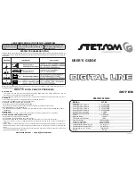
SPECIFICATIONS
USER’S GUIDE
3K7 ES
MODEL:
3K7 ES
Channels:
1
Power @ 13,8V 2 Ohms:
1 x 4.100W RMS
Power @ 13,8V 4 Ohms:
1 x 2.500W RMS
Power @ 12,6V 2 Ohms:
1 x 3.700W RMS
Power @ 12,6V 4 Ohms:
1 x 2.100W RMS
Minimum Work Impednce:
2 OHMS
Minimum Input Aenaitivity:
0,2V
Power:
9,5 to 15Volts
Signal to Noise:
>90dB
Total Harmonic Distortion:
< 0,9%
Freq. Response:
10Hz to 10KHz
Crossover High Pass:
10Hz to 700Hz
Crossover Low Pass:
50Hz to 10KHz
Comption Music Signal (12,6v):
3,5 to 183 A
Consumo Bass Signal (12,6v):
3,5 to 365 A
Dimensions (A x L x C) mm:
75x310x308
Weight:
4,0 Kg


