


43
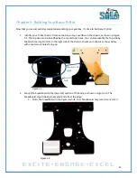
Chapter 5: Building Your Basic Pi-Bot
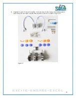
Now that you've successfully completed assembling your gearbox, it's time to build your Pi-Bot!
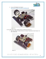
1.
Identify your Pi-Bot chassis. Remove the brown tape overlaid on the chassis, as shown in Figure
5.1. The top side can be identified by the countersink holes. You can also identify the top side by
the additional switch hole on the right side of the chassis. Orient your chassis as show below,
with countersunk holes facing up.
Figure 5.1
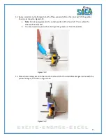
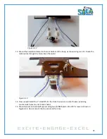
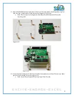
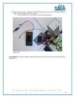
2.
Mount the breadboard to the lower left section of the body, as shown in Figure 5.2. The
breadboard should be approximated 3mm from the edge.
a.
Note: The breadboard in the figure is white. Your breadboard may come in any color!
Figure 5.2
Countersunk
holes
Switch
hole
Summary of Contents for Pi-Bot v2.00
Page 67: ...67 Figure 6 15 ...
Page 78: ...78 UltraSonicSensorTestwithLED Program ...
Page 80: ...80 ObstacleAvoidance Program ...
Page 82: ...82 ObstacleAvoidancewithLED Program ...
Page 83: ...83 ObstacleAvoidancewithLED Program CONTINUED ...
Page 90: ...90 Download and run the following program LineFollowing Program ...
Page 91: ...91 LineFollowing Program CONTINUED ...
Page 94: ...94 AdvancedLineFollowing Program CONTINUED ...
Page 95: ...95 AdvancedLineFollowing Program CONTINUED ...
Page 96: ...96 AdvancedLineFollowing Program CONTINUED ...
Page 110: ...Appendix B Complete Pi Bot Wiring Schematic ...


