background image


6935200020 


29


(SKY-MIG 453K, SKY-MIG 553S)


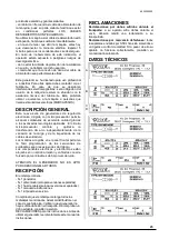
1) Encender el generador. 
2) Pulsar al mismo tiempo los botones PURGE e 
  INCH durante 3 segundos 


3) Los display mostran START “Str” y el tipo de 
  cebado seleccionado 


4) Pulsando el botón INCH se puede seleccionar el 
tipo de cebado deseado: LOW “Lo”, MEDIUM “ME”, 
HIGH “HI”. 
 
Después de 3 segundos el generador vuelve a la 
modalidad soldadura y es posible reanudar el soldeo.  


SELECIONAR PARAMETROS 
( velocidad de hilo/corriente ) 
 

Esta configuracion nos permite the poner los 
parametros de soldadura en funcion de velodidad 
de hilo o corriente de soldadura como la necesita 
al soldador. 
Para poder ver en la pantalla de derecha la 
velocidad de hilo o corriente necesita enceder 
l’equipo ( ON ) manteniendo pulsado el botón 
(INCH) para 2-3 secundos. 
En la pantalla de derecha puede ver el valor de 
velocidad de hilo o corriente. 
Si l’equipo vien parado y encendido tiene siempre 
en memoria la ultima impostacion. 


ELIMINACIÓN DE APARATOS 
ELÉCTRICOS Y 
ELECTRÓNICOS 

No  eliminar  nunca  los  aparatos 
eléctricos  junto  con  los  residuos 
normales.  Conforme  a  la  Directiva 
Europea 

2002/96/CE 

sobre 

residuos  de  aparatos  eléctricos  y 
electrónicos y relativa aplicación en 

el  ámbito  de  la  legislación  nacional,  los  aparatos 
eléctricos,  al  final  de  su  vida  útil,  deben  ser 
recogidos  separadamente  y  transportados  a  una 
planta  de  reciclaje.  Contactar  con  nuestro 
representante  de  zona  para  informarse  sobre  los 
sistemas de recogida. 
 
EN 

CASO 

DE 

MAL 

FUNCIONAMIENTO 

SOLICITAR  LA  INTERVENCIÓN  DE  PERSONAL 
CUALIFICADO. 
 

CICLO DE TRABAJO Y 
SOBRETEMPERATURA 

El ciclo de trabajo es el porcentaje de utilización de 
la  soldadora  sobre  10  minutos  que  el  operador 
debe  respetar  para  evitar  el  bloque  de  suministro 
por sobretemperatura. 
Si la máquina entra en sobretemperatura: 

el led amarillo parpadea 

es  necessario  esperar  aprox.  10  minutos 
para volver a soldar.  


Summary of Contents for SKY-MIG 353K

Page 1: ...SSMACHINE MANUAL DE INSTRUCCIONES PARA M QUINA DE SOLDAR SKY SKY SKY SKY MIG 353K MIG 353K MIG 353K MIG 353K 353S 353S 353S 353S SKY SKY SKY SKY MIG 453K MIG 453K MIG 453K MIG 453K 453S 453S 453S 453S...

Page 2: ...Castegnero Vicenza Italy Tel 39 0444 639525 Fax 39 0444 639682 www stelgroup it The following harmonized standard in force within the EEA has been used in the design EN 60974 1 ed 4 Arc welding equipm...

Page 3: ...ard in force within the EEA has been used in the design EN 60974 1 Arc welding equipment Part 1 Welding power sources EN 60974 10 Arc welding equipment Part 10 Electromagnetic compatibility EMC requir...

Page 4: ...a dei fumi Provvedere per una ventilazione adeguata dell area di lavoro Se la ventilazione non sufficiente usare un aspiratore che aspiri dal basso IL CALORE GLI SCHIZZI DEL METALLO FUSO E LE SCINTILL...

Page 5: ...tecnologie applicate Il circuito microprocessore controlla ed ottimizza il trasferimento dell arco indipendentemente dalla variazione del carico e dell impedenza dei cavi di saldatura I comandi sul p...

Page 6: ...one INSTALLAZIONE ATTENZIONE Questa apparecchiatura in CLASSE A non e destinata all uso in ambienti residenziali dove la potenza elettrica e fornita dal sistema pubblico di alimentazione a bassa tensi...

Page 7: ...llegare correttamente a terra l apparecchiatura pu provocare shock elettrici pericolosi per l utente e un non corretto funzionamento del generatore SOLLEVAMENTO ATTENZIONE SKY MIG 353K peso 87kg 191lb...

Page 8: ...ZIONI INTERNE per TOP 304 TS 1 Pulsante Spurgo Gas 2 Pulsante Avanzamento Filo SUB MENU SELEZIONE TIPO PARTENZA Questo tipo di settaggio permette di ottimizzare la fase di innesco a seconda delle esig...

Page 9: ...ilo o corrente Se il generatore viene spento e riacceso mantiene in memoria l ultima impostazione SMALTIMENTO APPARECCHIATURE ELETTRICHE ED ELETTRONICHE Non smaltire le apparecchiature elettriche assi...

Page 10: ...ause burns Keep the tip of the electrode far from your body and from other persons PREVENTION OF ELECTRIC SHOCKS Take the following precautions when working with a welding machine keep yourself and yo...

Page 11: ...and of the impedance of the welding cables The controls on the front panel allow easy programming of the welding sequences depending on the operating requirements The electronic components are enclos...

Page 12: ...ower supply voltage Maximum power supply current Maximum effective power supply current identifies the line fuse D OTHER CHARACTERISTICS Degree of protection INSTALLATION WARNING This Class A equipmen...

Page 13: ...er with a slow burning type fuse s In the event of damage to the power cable replacement or repair must be performed by a qualified person at an approved service centre EARTHING To ensure user protect...

Page 14: ...MIG 2T welding mode indicating led FRONT PANEL DESCRIPTION SKY MIG 453K 553S 1 Machine live led 2 Overtemperature Led 3 Thickness Voltage Display 4 Voltage Led 5 Thickness Led 6 Wire Speed Welding Cu...

Page 15: ...seconds the button PURGE and INCH 3 The displays show START Str and the type of start selected 4 Pressing INCH button is possible select the type of start LOW Lo MEDIUM ME HIGH HI After 3 seconds the...

Page 16: ...s the owner of the equipment you should get information on approved collection systems from our local representative By applying this European Directive you will improve the environment and human heal...

Page 17: ...chutzbrille Tragen Sie angemessene Kleidung Handschuhe und Schuhwerk Benutzen Sie Kopfschutzhauben mit geschlossenen Seiten sowie Linsen und Schutzgl ser gem Standard Schutzstufe DIN 10 Weisen Sie Per...

Page 18: ...s Problem mit Hilfe des technischen Kundendiensts des Herstellers zu l sen ALLGEMEINE EIGENSCHAFTEN Diese neue Reihe von Schwei ger ten ist mit einer elektronischen Stabilisierung ausgestattet welche...

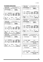
Page 19: ...6935200020 19 TECHNISCHE DATEN A C D B...

Page 20: ...chts die Luftzirkulation die durch den eingebauten L fter gesichert wird behindert Die inneren Bauteile ben tigen eine ausreichende K hlung Stellen Sie sicher dass der L fter keine Ablagerungen oder S...

Page 21: ...rahtr ckbrandzeit Gasnachstr mzeit 8 Encoder zur Reguilierung des Spannung Funktionsparameter 9 Encoder zur Regulierung des Drahtgeschwindikeit 10 Taste zur Wahl des Schwei modus 11 Led Anzeige MIG 4...

Page 22: ...dann lassen Sie den Knopf los Die Led Anzeige des gew hlten Modus wird dann blinken und HS anzeigen Nun k nnen Sie den hot start von 0 bis 50 des gew hlten Schwei stroms mit Encoder 6 max 400A einste...

Page 23: ...ndler Informationen ber ein lokales autorisiertes Sammel bzw Entsorgungssystem einholen Indem Sie diese Europ ische Richtlinie befolgen helfen Sie mit bei der Verbesserung der Umweltbedingungen und de...

Page 24: ...iadamente para evitar da os TANTO LOS HUMOS COMO LOS GASES PUEDEN CAUSAR DA OS A SU SALUD Alejar la cabeza de las emanaciones de humos Disponer una buena ventilaci n del rea de trabajo De no ser sufic...

Page 25: ...ad gracias a las avanzadas tecnolog as aplicadas El circuito microprocesador controla y optimiza la transferencia del arco independientemente de la variaci n de la carga y de la impedancia de los cabl...

Page 26: ...en edificios residenciales conectados directamente a la red p blica de BT Podr an presentarse dificultades potenciales para garantizar la compatibilidad electromagn tica en dichos ambientes a causa de...

Page 27: ...namiento incorrecto del generador LEVANTAMIENTO ATENCI N SKY MIG 353K peso 87kg 191lbs SKY MIG 453K peso 105kg 231lbs SKY MIG 353S TOP 304TS peso 128kg 282lbs SKY MIG 453S TOP 304TS peso 128kg 282lbs...

Page 28: ...dad del hilo DESCRIPCI N DE LAS REGULACIONES INTERNAS para TOP 304 TS 1 Bot n purga gas 2 Bot n avance hilo SUB MEN SELECCI N DEL TIPO DE CEBADO Este tipo de configuraci n permite optimizar la fase de...

Page 29: ...de hilo o corriente Si l equipo vien parado y encendido tiene siempre en memoria la ultima impostacion ELIMINACI N DE APARATOS EL CTRICOS Y ELECTR NICOS No eliminar nunca los aparatos el ctricos junto...

Page 30: ...5 1 5 6 5 3 5 7 5 4 6 2 6 2 8 6 6 4 7 8 6 5 7 7 7 2 12 7 4 10 4 7 6 10 2 8 3 15 6 8 5 13 5 8 9 4 17 8 9 6 16 5 9 10 5 20 10 8 18 8 10 WIRE 1mm Fe GAS Mixture 82 Ar 18 CO2 A B C D E F D E F D E F 1 0 8...

Page 31: ...4 1 0 1 2 1 0 1 1 1 0 1 10 2 0 1 8 2 0 1 6 2 0 2 4 3 0 2 1 3 0 1 8 3 0 2 8 4 0 2 4 4 0 1 10 4 0 2 10 5 0 2 5 5 0 2 1 5 0 WIRE 1 2mm Fe GAS Mixture 82 Ar 18 CO2 A B C D E F D E F D E F 1 10 2 0 1 8 2 0...

Page 32: ...SKY MIG 453S WIRE 0 8mm Fe GAS Mixture 82 Ar 18 CO2 A B C D E F D E F D E F 1 7 1 4 3 1 2 0 8 1 8 1 2 0 8 2 2 5 2 9 4 1 6 1 3 2 1 5 1 2 8 2 10 3 13 6 1 8 2 3 6 1 9 2 4 3 1 4 14 3 1 10 2 4 4 2 1 3 5 4...

Page 33: ...E F D E F 1 3 1 5 0 1 1 1 0 2 1 1 1 0 2 1 10 2 0 1 2 1 5 0 3 1 2 1 5 0 3 2 8 3 0 1 3 2 0 3 1 3 2 0 3 3 2 5 0 1 4 3 0 2 1 4 3 0 2 3 5 6 0 1 5 4 0 1 1 5 4 0 1 WIRE 1mm Fe GAS Mixture 82 Ar 18 CO2 A B C...

Page 34: ...E F 1 3 1 5 0 1 1 1 5 0 1 1 2 0 1 9 2 0 1 2 1 5 0 1 2 2 0 2 9 3 0 1 3 2 0 1 3 3 0 3 2 5 0 1 4 2 0 1 4 3 0 1 3 4 6 0 1 5 3 0 1 5 3 0 1 3 6 8 0 1 6 3 0 1 6 4 0 1 WIRE 1 2mm INOX GAS Mixture 98 Ar 2 CO2...

Page 35: ...6935200020 35 WIRING DIAGRAM SKY MIG 353K SKY MIG 453K...

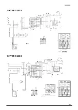
Page 36: ...6935200020 36 SKY MIG 353S SKY MIG 453S...

Page 37: ...6935200020 37 SKY MIG 553S TOP 304 TS...

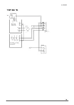
Page 38: ...6935200020 38 TOP 504 TS...

Page 39: ...14 15 16 17 18 19 20 21 22 23 2 R Plate SF 170 200 PA66GF50 Pressure arm 30mm Assembly Pressure adjustment unit Retaining screw Wire inlet guide PA66 ID 3 0 L 40 Torch adapter Connecting screw M12x1...

Page 40: ...Gear to motor Intermediary gear Gear with main axel Pressure arm 30mm assembly left Pressure arm 30mm assembly right Pressure adjustment unit red Retaining screw Wire inlet guide PA66 ID 3 0 L 40 Wire...

Page 41: ...or pressure arm left Torsion Spring for pressure arm right Pressure adjustment unit red Pan head screw M5x10mm Intermediate wire guide Drive gear 37mm Coverplate Retaining screw Torch adapter Connecti...

Page 42: ...935200020 42 CONNECTIONS MACHINE FRONT CONNECTIONS 1 2 3 4 5 6 3 4 2 6 5 N DESCRIPTION 1 TORCH CONNECTION 2 ON OFF 3 COMM 3 STEP not available on 353K 4 COMM 10 STEP 5 XL 1 not available on 353K 6 XL...

Page 43: ...SE 1 3 FUSE 2 4 AWC OPTIONAL OPTIONAL 5 14 PIN 6 POSITIVE 7 COOLING LIQUID CONNECTION OPTIONAL 8 COOLING LIQUID CONNECTION OPTIONAL WATER COOLER 4 PIN CONNECTOR PIN DESCRIPTION 1 Power supply common 2...

Page 44: ...CONNECTIONS WIRE FEEDER REAR CONNECTIONS 1 2 3 4 N DESCRIPTION 1 14 PIN 2 GAS 3 POSITIVE 4 COOLING LIQUID INPUT 5 COOLING LIQUID OUTPUT 5 1 3 2 N DESCRIPTION 1 TORCH CONNECTION 2 COOLING LIQUID CONNEC...

Page 45: ...6935200020 45 Info www stelgroup it tel 39 0444 639525...

Reviews: