11
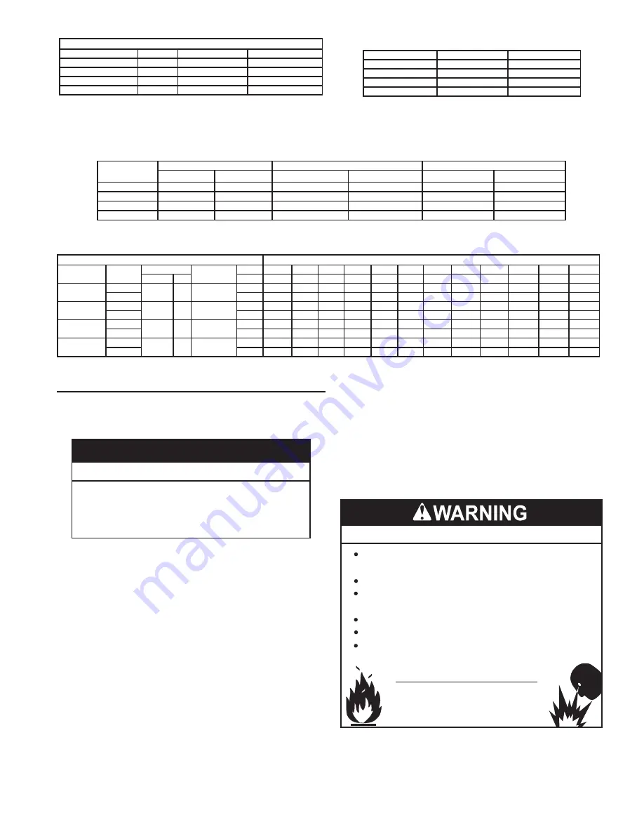
Table 4. GAS PRESSURE REQUIREMENTS
Model
*Manifold Pressure
Minimum Supply Pressure
Maximum Supply Pressure
NATURAL GAS PROPANE GAS
NATURAL GAS
PROPANE GAS
NATURAL GAS
PROPANE GAS
SUF 60120
0" W.C. (0 kPa) 0" W.C. (0 kPa)
3.5” W. C. (1.10 kPa) 8.5” W. C. (2.12 kPa) 14” W. C. (3.49 kPa) 14” W. C. (3.49 kPa)
SUF 100150
0" W.C. (0 kPa) 0" W.C. (0 kPa)
3.5” W. C. (1.10 kPa) 8.5” W. C. (2.12 kPa) 14” W. C. (3.49 kPa) 14” W. C. (3.49 kPa)
SUF 100199
0” W. C. (0 kPa) 0” W. C. (0 kPa) 3.5” W. C. (1.10 kPa) 8.5” W. C. (2.12 kPa) 14” W. C. (3.49 kPa 14” W. C. (3.49 kPa)
SUF 100250
0” W. C. (0 kPa) 0” W. C. (0 kPa) 3.5” W. C. (1.10 kPa) 8.5” W. C. (2.12 kPa) 14” W. C. (3.49 kPa) 14” W. C. (3.49 kPa)
Table 5. RECOVERY CAPACITIES
U. S. Gallons/hr & liters/hr at temperature rise indicated
Model
Type of
Gas
Input
Thermal
Efficiency%
°F
30°F
40°F
50°F
60°F
70°F
80°F
90°F
100°F 110°F 120°F
130°F
140°F
Btu/hr kW
°C
17°C
22°C 28°C 33°C
39°C 44°C
50°C
56°C
61°C
67°C
72°C
78°C
SUF 60120
Natural
120,000 35
95
GPH
461
345
276
230
197
173
154
138
126
115
106
99
Propane
LPH
1743
1308 1046
872
747
654
581
523
475
436
402
374
SUF 100150 Natural
150,000
44
98
GPH
594
445
356
297
255
223
198
178
162
148
137
127
Propane
LPH
2248
1686 1349
1124
963
843
749
674
613
562
519
482
SUF 100199 Natural
199,900
58
97
GPH
783
588
470
392
336
294
261
235
214
196
181
168
Propane
LPH
2965
2224 1779
1483
1271
1112
988
890
809
741
684
635
SUF 100250 Natural
250,000 73
96
GPH
970
727
582
485
416
364
323
291
264
242
224
208
Propane
LPH
3670
2753
2202
1835
1573 1376
1223
1101
1001
918
847
786
Table 3. Storage Capacities
MODEL
U. S. GALLONS
LITERS
SUF 60120
60
227
SUF 100150
100
379
SUF 100199
100
379
SUF 100250
100
379
Table 2. Fuel Type/Connection Size by Model
† MODEL
SERIES
NATURAL GAS
PROPANE GAS
SUF 60120
300/301
3/4 "NPT
3/4 "NPT
SUF 100150
300/301
3/4 "NPT
3/4 "NPT
SUF 100199
300/301
3/4 "NPT
3/4 "NPT
SUF 100250
300/301
3/4 "NPT
3/4 "NPT
† Depending on the installed equivalent length, and/or the number of appliances con-
nected, the supply gas line size may have to be increased beyond the minimum re-
quired sizes - see
LOCATING THE WATER HEATER
Carefully choose a location for the new water heater. The
placement is a very important consideration for the safety of the
occupants in the building and for the most economical use of the
water heater.
Property Damage Hazard
All water heaters eventually leak.
•
Do not install without adequate drainage.
•
CAUTION
Whether replacing an existing water heater or installing the water
heater in a new location observe the following critical points:
1.
The water heater must be located indoors.
2.
The water heater must not be located in an area where it will
be subject to freezing temperatures.
3. Locate the water heater so it is protected and not subject to
physical damage by a moving vehicle.
4.
Locate the water heater on a level surface.
5.
Locate the water heater near a floor drain. The water heater
should be located in an area where leakage of the tank or
connections will not result in damage to the area adjacent to
the water heater or to lower floors of the structure. When such
locations cannot be avoided, it is recommended that a metal
drain pan, adequately drained, be installed under the water
heater.
6. Locate the water heater close to the point of major hot water
usage.
7.
Locate the water heater close to a 120 VAC power supply. See
8.
Locate the water heater where an adequate supply of fresh
air for combustion and ventilation can be obtained. See
9.
Locate the water heater where the vent and intake air piping,
when installed, will remain within the maximum equivalent
10.
Do not locate the water heater where noise (such as
the Combustion Blower) during normal operation will be
objectionable in adjacent areas.
11.
Do not locate the water heater where the subsequent installation
of the vent (exhaust) or intake air terminations would be
objectionable due to noise at the termination(s). This includes
locations close to or across from windows and doors. See
Fire or Explosion Hazard
Read instruction manual before
installing, using or servicing
water heater.
Avoid all ignition sources if you smell gas.
Do not store or use gasoline or other flammable vapors and
liquids in the vicinity of this or any other appliance.
Use only the gas shown on the water heater rating label.
Keep ignition sources away from faucets after extended
periods of non-use.
Maintain required clearances to combustibles.
Do not expose water heater controls to excessive gas
pressure.
There is a risk in using fuel burning appliances such as gas water
heaters in rooms, garages or other areas where gasoline, other
flammable liquids or engine driven equipment or vehicles are
stored, operated or repaired. Flammable vapors are heavy and
travel along the floor and may be ignited by the water heater’s
igniter or Main Burner flames causing fire or explosion.
Summary of Contents for SUF 60120 THRU
Page 67: ...67 WIRING DIAGRAM Figure 67 Wiring Diagram...
Page 77: ...77 NOTES...
Page 78: ...78 NOTES...
Page 79: ...79 NOTES...


