background image

Instruction Manual

16

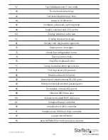
53

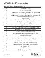
Initialize time value in 40h; BIOS area.

60

Setup virus protection according to setup.

61

Set system speed for boot.

62

Setup NumLock status according to setup.

63

Boot attempt (set low stack, and boot via INT 19H).

B0

Spurious (if interrupt occurs in protected mode).

B1

Unclaimed NMI (if NMI occurs, press F1 to disable NMI, F2 for reboot).

E1-EF

Setup pages (E1 - page 1, E2 - page 2, ... etc).

FF

Boot the operating system.

Summary of Contents for PCIPOST

Page 1: ...eitung de startech com FR Guide de l utilisateur fr startech com ES Guía del usuario es startech com IT Guida per l uso it startech com NL Gebruiksaanwijzing nl startech com PT Guia do usuário pt startech com PCIPOST PCI POST PC System Diagnostics Test Card 2 x 7 Segment LED actual product may vary from photos ...

Page 2: ...receiving antenna Increase the separation between the equipment and receiver Connect the equipment into an outlet on a circuit different from that to which the receiver is connected Consult the dealer or an experienced radio TV technician for help Use ofTrademarks RegisteredTrademarks and other Protected Names and Symbols This manual may make reference to trademarks registered trademarks and other...

Page 3: ... Begin 2 Installation 2 Using Your Card 3 Quick Error Reference Guide 4 AMI BIOS POST Test Codes 5 AMI WinBIOS HiFLEX 101094 5 Runtime code is uncompressed in F000 shadow ram 6 AWARD BIOS POST Test Code Listing 14 Phoenix BIOS POST Test Code Listing 17 Technical Support 22 Warranty Information 22 ...

Page 4: ...bleshooting steps and preventing non defective parts from being replaced Backed by Lifetime Warranty and free lifetime technical support StarTech com s PCI Post card is designed and constructed to provide reliable computer diagnostics Please Note You may have to refer to your motherboard manufacturer s manual for motherboard specific error diagnostic codes when using the PCI Post card Packaging Co...

Page 5: ...otherboard manufacturer if you encounter any difficulties The PCIPOST is compatible with every IBM compatible system but since there are numerous BIOS versions and suppliers you may not find your system BIOS information in the error code listing This information may be available in your motherboard manufacturer s user guide Your BIOS manufacturer can likely supply you with this information if you ...

Page 6: ... LED does not light there is a problem with the reset If the D2 LED does not light there is a problem with the system clock The BIOS will then initialize verify and test numerous functions in your computer Every initialization verification and test is its own separate program with its own error code As the BIOS scrolls through these processes you will see these error codes flashing across the LEDs...

Page 7: ...e CPU 2 Replace CPU if NPU is built in CPU Memory 13 20 24 D1 D3 20 40 58 C1 08 31 32 09 1F 1C 20 28 2C 32 3A 60 68 1 Check and clean RAM module 2 Replace RAM module Display Card 2C 34 2C 34 0D 0E 2B 33 46 1 Check and clean display card slot and golden finger 2 Replace display card M B error Others DIY Code Others DIY Code Others DIY Code Others DIY Code Others DIY Code Call Customer service cente...

Page 8: ...lization before keyboard BAT is to be done next CD BAT command to keyboard controller is to be issued CE Keyboard controller BAT result verified Any initialization after KB controller BAT is to be done next CF Initialization after KB controller BAT done Keyboard command byte is to be written next D1 Keyboard controller command byte is written Going to check pressing of INS key during power on D2 C...

Page 9: ...is to begin 0A CMOS initialization done if any CMOS status about to initialize for Data and Time 0B CMOS status register initialization done Any initialization before keyboard BAT is to be done next 0C KB controller I B free Going to issue the BAT command to the keyboard controller 0D BAT command to keyboard controller is issued Going to verify the BAT command 0E Keyboard controller BAT result ver...

Page 10: ... done Going to read input port of 8042 for turbo switch and to clear password if post diag switch is on 26 Input port of 8042 is read Going to initialize global data for turbo switch 27 Global data initialization for turbo switch is over Any initialization before setting video mode is to be done next 28 Initialization before setting video mode is complete Going for monochrome mode and colour mode ...

Page 11: ...mode memory test about to start 40 Going to prepare the descriptor tables 42 Descriptor tables prepared Going to enter in Virtual mode for memory test 43 Entered in the virtual mode Going to enable interrupts for diagnostics mode 44 Interrupts enabled if diagnostics switch is on Going to initialize data to check memory wrap around at 0 0 45 Data initialized Going to check for memory wrap around at...

Page 12: ...ove 1M complete Going to save memory size information 53 Memory size information is saved CPU registers are saved Going to enter in real mode 54 Shutdown successful CPU in real mode Going to disable gate A20 line and disable parity NMI 57 A20 address line parity NMI disable successful Going to adjust memory size depending on relocation shadow 58 Memory size adjusted for relocation shadow Going to ...

Page 13: ...etup complete Going to uncompress SETUP code and execute CMOS setup 88 Returned from CMOS setup program and screen is cleared About to do programming after setup 89 Programming after setup complete Going to display power on screen message 8B First screen message displayed WAIT message displayed About to do Video BIOS shadow 8C Video BIOS shadow successful Setup options programming after CMOS setup...

Page 14: ...ize the coprocessor next 9D Coprocessor initialized Going to do any initialization after coprocessor test 9E Initialization after coprocessor test is complete Going to check extended keyboard keyboard ID and num lock 9F Extended keyboard check is done ID flag set and num lock on off Keyboard ID command to be issued A0 Keyboard ID command issued Keyboard ID flag reset A1 Keyboard ID flag reset Cach...

Page 15: ...fic area 00 Copying of code to specific area done Going to give control to INT 19 boot loader The system BIOS gives control to various BUSes at the following checkpoints to do various tasks on different BUSes POST Code AMI HiFLEX BIOS WinBIOS Checkpoints of the BUSes 2A Different BUSes initialization to start if present 38 Different BUSes initialization to start if present 39 Display different BUS...

Page 16: ...ble X indicates the function is being executed X can be from 0 to 7 0 func 0 disable all devices on the BUS concerned 1 func 1 static devices initialized on the BUS concerned 2 func 2 output devices initialized on the BUS concerned 3 func 3 input device initialized on the BUS concerned 4 func 4 IPL device initialized on the BUS concerned 5 func 5 general device initialized on the BUS concerned 6 f...

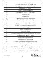
Page 17: ... defaults C1 Memory presence test OEM specific test to size on board memory C5 Early shadow OEM specific early shadow enabled for fast boot C6 Cache presence test external cache size detection 08 Setup low memory base 64K memory test 09 TEST CMOS RAM checksum load default value is test is bad 0A Setup interrupt vector table 0B Test CMOS RAM checksum and load default value if test is bad 0C Initial...

Page 18: ...Test base memory and extended memory 32 Test EISA extended memory Skip in ISA mode 3C Setup enabled 3D Initialize and setup mouse 3E Setup cache controller BF Chipset initialization program chipset registers with setup values 40 Display virus protest disabled or enabled 41 Initialize floppy drive and controller 42 Initialize hard drive and controller 43 Detect and initialize the serial parallel an...

Page 19: ...1 Set system speed for boot 62 Setup NumLock status according to setup 63 Boot attempt set low stack and boot via INT 19H B0 Spurious if interrupt occurs in protected mode B1 Unclaimed NMI if NMI occurs press F1 to disable NMI F2 for reboot E1 EF Setup pages E1 page 1 E2 page 2 etc FF Boot the operating system ...

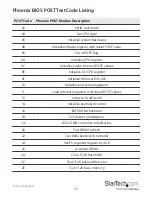
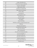
Page 20: ... initial POST values 0E Initialize I O CPU register 0F Initialize the local BUS IDE 10 Initialize power management 11 Load alternate registers with initial POST values 12 Jump to UserPatch0 14 Initialize keyboard control 16 BIOS ROM checksum 18 5254 timer initialization 1A 8237 DMA controller initialization 20 Test DRAM refresh 22 Test 8042 keyboard controller 24 Set ES segment register to 4 GB 26...

Page 21: ... CPU speed 42 Initialize interrupt vectors 44 Initialize BIOS interrupts 46 Check ROM copyright notice 47 Initialize manager for PCI option ROMs 48 Check video configuration against CMOS 49 Initialize PCI BUS and devices 4A Initialize all video adapters in system 4C Shadow video BIOS ROM 4E Display copyright notice 50 Display CPU type and speed 51 Initialize EISA board 52 Test keyboard 54 Set key ...

Page 22: ...nfiguration errors 74 Test real time clock 76 Check for keyboard error 7C Setup hardware interrupt vectors 7E Test coprocessor if present 80 Disable onboard I O ports 82 Detect and install external RS 232 ports 84 Detect and install external parallel ports 86 Reinitialize onboard I O ports 88 Initialize BIOS data area 8A Initialize extended BIOS data area 8C Initialize floppy controller 90 Initial...

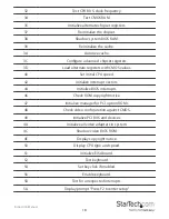
Page 23: ...matic rate A8 Ease F2 prompt AA Scan for F2 stroke AC Enter SETUP AE Clear in POST flag B2 POST done prepare to boot operating system B4 One beep B6 Check password option B8 Clear global descriptor table BC Clear parity checkers BE Clear screen option BF Clear virus and backup remainders C0 Try to boot with INT 19 D0 Interrupt handler error D2 Unknown interrupt error D4 Pending interrupt error D6 ...

Page 24: ...tion E2 Initialize the chipset E3 Initialize refresh counter E4 Check for forced Flash E5 Check H W status ROM E6 BIOS ROM is OK E7 Do a complete RAM test E8 Do OEM initialization E9 Initialize interrupt controller EA Read in the bootstrap code EB Initialize all vectors EC Boot the Flash program ED Initialize the boot device EE Boot code was read OK ...

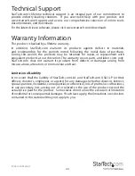
Page 25: ...e returned for repair or replacement with equivalent products at our discretion The warranty covers parts and labor costs only StarTech com does not warrant its products from defects or damages arising from misuse abuse alteration or normal wear and tear Limitation of Liability In no event shall the liability of StarTech com Ltd and StarTech com USA LLP or their officers directors employees or age...

Page 26: ...rts and we quickly deliver them wherever they need to go Just talk to one of our tech advisors or visit our website You ll be connected to the products you need in no time Visit www startech com for complete information on all StarTech com products and to access exclusive resources and time saving tools StarTech com is an ISO 9001 Registered manufacturer of connectivity and technology parts StarTe...

Reviews: