3-10
BKSU & Main Board Unit Assembly
Chapter 3 - Installation
STARPLUS STSe - Installation Manual
August 2005
BKSU & Main Board Unit Assembly
The BKSU includes the fixed DTIB in slot 0, a fixed LCOB in slot 1, and a SLIB2 in slot 2. This
provides an initial capability of four CO lines, eight digital telephone stations, and two single
line telephone stations. Additional cards/boards can be added to increase capability.
The BKSU provides the following miscellaneous features:
1 external page port that is connected to a transformer, providing a 600-ohm impedance.
1 music input that is connected to a transformer, providing a 600-ohm impedance.
1 independent dry relay contact rated at 1 amp, 24V DC.
2 DTMF receivers.
These features are provided through the CO amphenol “Champ” connector on the right side
of the BKSU. These features are controlled by system software.
Main Board Unit
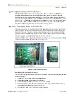
The Main Board Unit (MBU) is installed in the BKSU at the factory before the shipment. The MBU
contains a lithium dry cell to maintain memory and real-time clock functions.
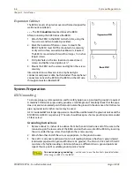
The MBU can be equipped with 3 daughter boards: MODU for modem access to the system,
PLLU, and CIDU for Caller ID (refer to
“Expansion Board Installation” on page 3-13
software is contained on two chips labeled U1 and U2.
The battery is soldered to the MBU and connected to the circuitry by an ON-OFF dip switch
(SW4).
»
Make sure that dip switch SW4 is turned to ON before programming the system database.
Initialize Default Settings
Before programming the system, switch 8 (SW5) should be placed in the ON position and
powered off and on to initialize the system database to default.
Retain Database
Once the database is initialized, switch 8 (SW5) should be placed in the OFF position to protect
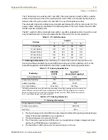
the database. The following diagram shows the dip switch position as they relate to the
“database” functions:
MBU PCB
Marking
Dip Switch
Position
Function
8
7
6
5
4
3
2
1
SW8
OFF
ON
Retain the database
Flush the database
OFF
Ç
ON
È
Summary of Contents for STSe Key System
Page 1: ...August 2005 Issue 1 0 STARPLUS STSe Key Systems Installation Manual TM...
Page 4: ......
Page 10: ...vi Figures STARPLUS STSe Installation Manual August 2005...
Page 12: ...viii Tables STARPLUS STSe Installation Manual August 2005...
Page 14: ...N O T E S...
Page 22: ...N O T E S...
Page 30: ...N O T E S...
Page 68: ...3 40 Door Box Chapter 3 Installation STARPLUS STSe Installation Manual August 2005...
Page 70: ...N O T E S...
Page 94: ...iv Index STARPLUS STSe Installation Manual August 2005...

