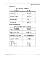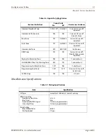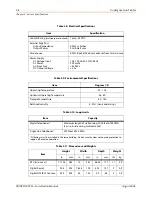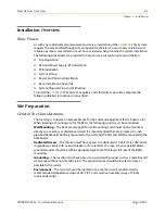
3-6
System Preparation
Chapter 3 - Installation
STARPLUS STSe - Installation Manual
August 2005
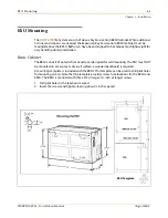
Expansion Cabinet
The EKSU consists of a plastic cover and frame designed for
wall mount installation.
» » » The EKSU
must be
mounted above the BKSU.
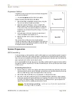
After positioning the EKSU above the BKSU:
1. Attach the EKSU to the BKSU on both sides, using the
four screws and two brackets provided.
2. Mark the location of the two screws to mount the
BKSU.The EKSU must NOT be mounted on a masonry
or dry wall surface; a wooden backboard is required.
The EKSU is mounted with two #10 or larger, 1½ inch or
longer screws.
3. Drill pilot holes in the two locations marked, insert
screws and tighten, leaving about ½”.
4. Mount the EKSU on the screws and tighten the screws
securely.
Interconnection is achieved via an amphenol-type
connector and power cable, both included. The amphenol
connector connects the EKSU to the BKSU on the left side
through connectors labeled EXP.
System Preparation
KSU Grounding
To ensure proper system operation and for safety purposes, a good earth ground is required.
A metallic COLD water pipe usually provides a reliable ground. Carefully check that the pipe
does not contain insulated joints that could isolate the ground. In the absence of a COLD water
pipe, a ground rod or other source may be used.
A #12 insulated AWG or larger copper wire should be used between the ground source and the
KSU (BKSU and EKSU, respectively). The wire should be kept as short as possible (recommended
25 feet or less).
Grounding Instructions
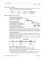
1. Remove about 1½ inches of insulation from both ends. Attach one end of the wire to the
Ground Lug on the lower side of the BKSU and on the lower side of the EKSU by inserting
the wire under the lug screw, then tighten the screw securely.
2. Attach the other end of the wire, as appropriate, to the ground source.
3. Take a DC resistance reading and an AC volt reading between the chassis ground point
(cold water pipe) and AC ground (third wire AC ground). The limit is 5V AC and 5 Ohms DC
resistance. If a higher reading is obtained, choose a different chassis ground point and
repeat this step until a suitable ground point is found.
To ensure proper grounding
… make sure to use the brackets provided when
attaching an EKSU to the BKSU.
Summary of Contents for STSe Key System
Page 1: ...August 2005 Issue 1 0 STARPLUS STSe Key Systems Installation Manual TM...
Page 4: ......
Page 10: ...vi Figures STARPLUS STSe Installation Manual August 2005...
Page 12: ...viii Tables STARPLUS STSe Installation Manual August 2005...
Page 14: ...N O T E S...
Page 22: ...N O T E S...
Page 30: ...N O T E S...
Page 68: ...3 40 Door Box Chapter 3 Installation STARPLUS STSe Installation Manual August 2005...
Page 70: ...N O T E S...
Page 94: ...iv Index STARPLUS STSe Installation Manual August 2005...

