background image

SR4 Series User Manual

4

4. Hardware Installation Procedure

Please follow the instructions below to complete the hardware installation.

Place the system on a stable surface. Ensure that it is well ventilated without blockage to 

the vent and kept away from areas near water and damage prone areas.
Use the ejector pin included in the accessory kit and inserted into the pin release opening to 

eject the removable drive tray latch and extract the removable drive tray.
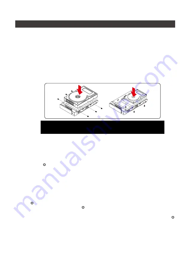
For 3.5" HDD/SSD, please secure it by use six the larger screws included in the accessory 

kit. For 2.5" HDD/SSD, please secure it by use four the smaller screws included in the 

accessory kit.
When the hard drive installation has been completed, insert the hard drive tray into the 

system horizontally and secure the latch into place.

Step 1

Step 2

Step 3

Step 4

Step 5

Step 6

Step 7

Step 8

Step 9

Step 10

Step 11

Connect the power cable to the SR4, and then plug the power to the wall socket. Boot-up 

the unit. 
Connect the USB cable to the computer and the SR4 relevant port respectively.
First turn 

the power main switch on the back of the product

 to “I” to turn the power on, 

then gently press 

the power touch switch on the front of the product

 until the power 

symbol " " will light red.
Set the storage mode using the LCD and buttons on the front (please refer to section 5 for 

front panel and LCD information).
After boot-up, your operating system will automatically detect the storage capacity of your 

hard drives. Please follow the operating system instructions to configure and format your 

drives. The formatted drives can be configured for the RAID setup.

If the product is not in use at the moment, the product can be put into power-off mode: 

first press 

the power touch switcth on the front of the product

 until the power symbol 

"

" turns to red; to use the product, press 

the power touch switcth on the front of the 

product

 until the power symbol " " turns to blue.

If the product is not used for a long time, please turn off the product main power switch: first 

gently press the power touch switch on the front of the product until the power symbol " " 

turns to red, then turn the power main switch on the back of the product to "O" to turn off the 

power. 

Note: Please avoid using hard disk drives from different manufacturers or different 

models from the same manufacturer as this may impact system performance.

  The product is in a state of near-complete power-off in shutdown mode, and the hard disk, LCM, and fan are all 

out of operation, providing only a small portion of power for preparation for subsequent startup.

Summary of Contents for Sohoraid SR4

Page 1: ...SOHORAID User Manual SR4 Series NO SATA ...

Page 2: ...Port 16 7 Support USB Power Delivery SR4 B31 SR4 BA31 16 8 Replacement of Malfunctioning Drive and Data Rebuild Instructions 17 9 System Temperature Overheat and Fan Failure Management 17 10 Frequently Asked Questions 17 SafeTANK SR4 Series 無 SATA 產品使用說明 18 1 環境需求 18 2 產品外觀及包裝內容 18 3 硬體需求與注意事項 20 4 硬體安裝 21 5 前面板操作及 LCD 訊息說明 22 6 支援 Display 埠 33 7 支援 USB Power Delivery SR4 B31 SR4 BA31 33 8 故障硬碟更換步...

Page 3: ...STARDOM com tw for more information All product related content in this manual are copyrighted by STARDOM TECHNOLOGY INC Please check the product and accessories for any defect or missing parts If you have any questions please contact your product supplier Please visit the official website Download page http www stardom com tw STARDOM2016 download php to download drivers and other related resources ...

Page 4: ...nclosure handle C HDD enclosure pin release D LCM display E Power touch switch F System status light G UP button H DOWN button I ESC button J ENTER button K Fan L Mute button M Display port N USB 3 1 port O Power main switch P Power socket Q Fan speed switch R Anti theft lock High Low R ...

Page 5: ...ower supply It mainly to extend the Notebook s usage time Take Macbook Pro 13 as an example the original power supply is 60W assuming it take 2 hours for it to fully charge the battery use SR4 B31 SR4 BA31 might need three times time Therefore if user need to use Notebook for a long time it is recommended to connect the original power supply first before connect SR4 B31 SR4 BA31 6 Whenever turning...

Page 6: ... the front of the product until the power symbol will light red Set the storage mode using the LCD and buttons on the front please refer to section 5 for front panel and LCD information After boot up your operating system will automatically detect the storage capacity of your hard drives Please follow the operating system instructions to configure and format your drives The formatted drives can be...

Page 7: ...l 4 External 4BAY HARDWARE RAID Quick Setup Create One RAID RAID 0 RAID 5 Select Disk Delete All RAID Disk Manager Identify Disk Disk 1 Check Disk LED Disk 2 Check Disk LED Disk 3 Check Disk LED Disk 4 Check Disk LED Show Disk Info Disk Info RAID Manager Identify RAID Select RAID Create RAID RAID 0 RAID 5 Select Disk Delete RAID Select RAID RAID Info Change RAID Pwd Password for RAID Setup Rebuild...

Page 8: ...RE RAID Main Menu Quick Setup Main Menu Disk Manager Main Menu RAID Manager Main Menu System Manager Level 0 Level 1 SR4 Series User Manual 6 The following is the display status set for the first time P7 8 P9 P10 12 P13 15 ...

Page 9: ... Quick Setup Create One RAID Level 3 Level 4 SR4 Series User Manual 7 Note Note 1 If you don t want to set password please press ENTER to go to next step Note 2 If user forgot the password it will not be allowed to access the data from the storage or write new data into it STARDOM will not be held liable for the damage or loss of data you stored on the storage If you did not set password before pl...

Page 10: ...Level 1 Level 2 Disk Manager Identify Disk Disk Manager Show Disk Info Main Menu Disk Manager SR4 Series User Manual 8 ...

Page 11: ...sk Info Select Disk Disk 1 2 3 4 Disk Manager Identify Disk Disk Manager Disk 1 Disk 2 Disk Manager Disk Manager Check Disk LED Model Level 2 Level 3 Level 4 Disk 3 Disk Manager Disk 4 Disk Manager SR4 Series User Manual 9 ...

Page 12: ... Menu RAID Manager RAID Manager Identify RAID RAID Manager Create RAID RAID Manager Delete RAID RAID Manager RAID Info RAID Manager Change RAID Pwd RAID Manager Rebuilding Priority Level 2 SR4 Series User Manual 10 ...

Page 13: ...ID Setup Level 2 Level 3 Level 4 Are You Sure Enter Yes Esc No SR4 Series User Manual 11 ENTER Enter to next level or Confirm ESC Back to next level or Cancel UP Select HDD SSD DOWN Cancel the select HDD SSD Note Note 1 If you don t want to set password please press ENTER to go to next step Note 2 If user forgot the password it will not be allowed to access the data from the storage or write new d...

Page 14: ...ilding Priority Level 2 Level 3 Select Priority Medium Level Select Priority Low Level Select Priority Lowest Level Select Priority Highest Level Select Priority High Level Level 4 Select RAID SR4 Series User Manual 12 ...

Page 15: ...Level 2 System Manager System Info System Manager Changhe Password System Manager Logout From Menu System Manager Alarm Control System Manager Hardware Monitor Main Menu System Manager SR4 Series User Manual 13 ...

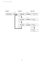
Page 16: ...anager Alarm Control for System Info Level 3 Level 4 Password SR4 Series User Manual 14 Note Note 1 If you don t want to set password please press ENTER to go to next step Note 2 If user forgot the password it will not be allowed to access the data from the storage or write new data into it STARDOM will not be held liable for the damage or loss of data you stored on the storage ...

Page 17: ...or Hardware Monitor Voltage Monitor Hardware Monitor Temp Monitor Hardware Monitor FAN Monitor 3 3V 5V 12V Voltage xxxxV Level 3 Level 4 Level 5 Temperature xx degrees FAN Speed xxxx RPM FAN Level LEVEL x SR4 Series User Manual 15 ...

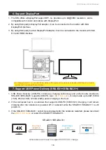
Page 18: ... C to C cable it can provide up to 24W 5V 3A 15W 9V 2A 18W 12V 2A 24W power charging to the host 2 If the connected host is a notebook that supports USB PD 5V 9V 12V charging it will remain charging after the notebook is powered off or restarted while the SR4 B31 SR4 BA31 is still power on 3 If the SR4 B31 SR4 BA31 cannot be recognized after the notebook restarted please reconnect the USB C to C c...

Page 19: ...e indicator stops the data rebuild process has been completed If the alarm indicator has lit up red and the audio alarm sounds this could mean that either a system fan has stopped operating entirely or the system temperature has exceeded over the default temperature of 55 C When this occurs you may press the mute button at the rear of the system to shut off the audio alarm and power off the system...

Page 20: ... STARDOM com tw 取得相關訊息 本手冊相關產品內容歸銳銨科技股份有限公司版權所有 1 環境需求 工作溫度 0 40 32 104 儲存溫度 20 47 4 116 相對濕度 5 至 95 非冷凝狀態 工作電壓 100 240V AC 請確認相關配件與產品本身是否有受損或配件缺少 若有任何疑問請與本產品供應商聯絡 請前往官網 產品資料下載頁面 http www stardom com tw STARDOM2016 download php 下載 驅動程式以及其餘相關資源 SR4 BA31 本體 X1 內含抽取盒 x4 SR4 B31 本體 X1 內含抽取盒 x4 SR4 B31A 本體 X1 內含抽取盒 x4 USB 3 2 C to C 連接線 x1 USB 3 2 C to C 連接線 x1 USB 3 2 C to A 連接線 x1 USB 3 2 C to A 連接線 ...

Page 21: ...ies User Manual 19 正面與背面示意圖 正面圖 背面圖 A 硬碟讀取燈 B 硬碟抽取盒把手 C 硬碟抽取盒頂針孔 D 液晶顯示器 E 電源觸碰開關 F 系統指示燈 G UP 按鍵 H DOWN 按鍵 I ESC 按鍵 J ENTER 按鍵 K 風扇 L 靜音開關 M Display 埠 N USB 3 1 連接埠 O 電源總開關 P 電源插座 Q 風扇轉速切換按鈕 R 防竊鎖孔 High Low R ...

Page 22: ... 並沒有資料存取的動作 5 SR4 B31 SR4 BA31 的 PD 功能 最多僅能提供 24W 主要在延長 Notebook 的使用時間 與 原本 Notebook 電源供應器的瓦數有落差 以 Macbook Pro 13 為例 電源供應器為 60W 假設使 用原本的電源供應器充飽電需要 2 小時 透過 SR4 B31 SR4 BA31 大約會需要 3 倍的時間 因 此如果需要長時間使用 Notebook 建議先接上 Notebook 原本的電源供應器後再接上 SR4 B31 SR4 BA31 6 當您需要關閉或移除 SR4 時 務必透過您所操作的作業系統中執行硬碟安全移除後 方進行電源 關閉的動作 7 強烈建議除了使用 SR4 的資料儲存功能外 請針對重要資料備份到另一個儲存裝置上或遠端備份 雙重備援您重要的資料 若您儲存在 SR4 的資料損毀或遺失 STARDOM 將不負任何的責任...

Page 23: ...腦與 SR4 相關連接埠 將產品背面的電源總開關扳動至 I 讓電源開啟後 產品正面的電源觸控開關會亮紅燈 再 輕壓產品正面的電源觸控開關 直到電源符號 轉變為藍燈 透過前方的 LCD 與按鍵來設定您所需求的儲存模式 請參考 前面板操作及 LCD 訊息說明 開機後 您的作業系統將會自動辨識到 RAID 容量 待辨識成功後 請依據您所需的儲存格 式 將系統內的硬碟依照作業系統的指示完成格式化 待格式化完成後 便可直接執行 RAID 系統 若暫時不使用產品 可讓產品進入關機模式 先輕壓產品正面的電源觸控開關 直到電源符 號 轉為紅燈 若要使用產品則輕壓產品正面的電源觸控開關 直到電源符號 轉為 藍燈 假使長時間不使用產品 則請將產品電源總開關關閉 先輕壓產品正面的電源觸控開關 直 到電源符號 燈號轉為紅燈 再將產品背面的電源總開關扳動至 O 讓電源關閉 步驟 5 步驟 6 步驟 7 步驟 8 步...

Page 24: ...ete RAID Select RAID RAID Info Change RAID Pwd Password for RAID Setup Rebuilding Priority Highest High Medium Low Lowest System Manager System Info Firmware Version Changhe Password Password for System Info Logout From Menu Y or N Alarm Control Mute the Buzzer Hardware Monitor Voltage Monitor 3 3V 5V 12V Temp Monitor Temp Fan Monitor Fan Speed Fan Level SR4 Series User Manual 22 5 前面板操作及 LCD 訊息說明...

Page 25: ...EXTERNAL 4 BAY HARDWARE RAID Main Menu Quick Setup Main Menu Disk Manager Main Menu RAID Manager Main Menu System Manager Level 0 Level 1 SR4 Series User Manual 23 以下為首次設定的顯示流程 P24 25 P26 P27 29 P30 32 ...

Page 26: ...el 2 Select Level RAID 0 Enter Password _ Enter Password _ Are You Sure Enter Yes Esc No Select Level RAID 5 Level 2 Quick Setup Create One RAID Level 3 Level 4 SR4 Series User Manual 24 若先前沒有設定密碼 按 ENTER 以進行下一個步驟 註 註 1 可以不設定密碼 按 ENTER 以進行下一個步驟 註 2 如果使用者忘記密碼 將無法讀取硬碟上的資料 或是將新資料寫入硬碟 若使用者儲存在 SR4 的資料損毀或遺失 STARDOM 將不負任何的責任 ...

Page 27: ...Level 1 Level 2 Disk Manager Identify Disk Disk Manager Show Disk Info Main Menu Disk Manager SR4 Series User Manual 25 ...

Page 28: ...k Info Select Disk Disk 1 2 3 4 Disk Manager Identify Disk Disk Manager Disk 1 Disk 2 Disk Manager Disk Manager Check Disk LED Model Level 2 Level 3 Level 4 Disk 3 Disk Manager Disk 4 Disk Manager SR4 Series User Manual 26 ...

Page 29: ... Menu RAID Manager RAID Manager Identify RAID RAID Manager Create RAID RAID Manager Delete RAID RAID Manager RAID Info RAID Manager Change RAID Pwd RAID Manager Rebuilding Priority Level 2 SR4 Series User Manual 27 ...

Page 30: ...RAID 0 RAID Manager RAID 5 RAID Manager Delete RAID RAID Manager RAID Information RAID Manager Change RAID Pwd Password for RAID Setup Level 2 Level 3 Level 4 Are You Sure Enter Yes Esc No SR4 Series User Manual 28 ENTER 進入下一層 或是 確認 ESC 跳回上一層 或是 取消 UP 指定硬碟 DOWN 取消被指定硬碟 註 註 1 可以不設定密碼 按 ENTER 以進行下一個步驟 註 2 如果使用者忘記密碼 將無法讀取硬碟上的資料 或是將新資料寫入硬碟 若使用者儲存在 SR4 的資料損毀或遺失 STARDOM 將不負任何的責任 ...

Page 31: ...ilding Priority Level 2 Level 3 Select Priority Medium Level Select Priority Low Level Select Priority Lowest Level Select Priority Highest Level Select Priority High Level Level 4 Select RAID SR4 Series User Manual 29 ...

Page 32: ...Level 2 System Manager System Info System Manager Changhe Password System Manager Logout From Menu System Manager Alarm Control System Manager Hardware Monitor Main Menu System Manager SR4 Series User Manual 30 ...

Page 33: ...zzer Enter Yes Esc No System Manager Changhe Password System Manager Logout From Menu System Manager Alarm Control for System Info Level 3 Level 4 Password SR4 Series User Manual 31 註 註 1 可以不設定密碼 按 ENTER 以進行下一個步驟 註 2 如果使用者忘記密碼 將無法讀取硬碟上的資料 或是將新資料寫入硬碟 若使用者儲存在 SR4 的資料損毀或遺失 STARDOM 將不負任何的責任 ...

Page 34: ...or Hardware Monitor Voltage Monitor Hardware Monitor Temp Monitor Hardware Monitor FAN Monitor 3 3V 5V 12V Voltage xxxxV Level 3 Level 4 Level 5 Temperature xx degrees FAN Speed xxxx RPM FAN Level LEVEL x SR4 Series User Manual 32 ...

Page 35: ... 連接線標準 SR4 B31 SR4 BA31 支援 USB PD 若採用 USB C to C 連接線 可提供 5V 3A 15W 9V 2A 18W 12V 2A 24W 電力給主機端 2 若所連接之主機端為支援 USB PD 5V 9V 12V 充電的筆記型電腦 在 SR4 B31 SR4 BA31 開 機的狀態下 將筆電關機或重新開機後 USB PD 仍會維持充電功能 3 如電腦無法讀取到 SR4 B31 SR4 BA31 請重新連接 USB C to C 連接線 或是將 SR4 B31 SR4 BA31 關機再啟動 方可正常連接使用 7 支援 USB Power Delivery SR4 B31 SR4 BA31 筆記型電腦需要支援 5V 9V 12V 充電 Notebook 4K 更高的畫質 K Hz 智慧充電 W SR4 B31 SR4 BA31 對於 DisplayPort...

Page 36: ...從抽取盒上拆解下來 2 將新的硬碟安裝至抽取盒後 再將新硬碟的抽取盒插回 SR4 空的硬碟槽位置 並將抽取盒門鎖上 確認硬碟已完全插入 3 RAID 5 模式下 將電源打開時 您將會看到所更換的新硬碟抽取盒旁的指示燈號呈現閃爍紅藍燈 的狀態 表示更換上的硬碟資料正在進行重建 此時 您仍可正常使用 SR4 工作 待資料重建指 示燈號停止 即代表資料重建完成 RAID 0 模式下 因單顆硬碟故障會造成所有資料損毀 更換 新硬碟後 請重新將系統內的硬碟格式化 SR4 內建故障警示功能 若 SR4 內部溫度超過 55 或 SR4 風扇發生故障時 內建的蜂鳴器會發出 警告聲響 前面板的紅色警示燈號也會亮起 此時您可選按系統背面的靜音按鈕 先將警示聲關閉 並在允許的狀況下關閉 SR4 電源讓系統降溫 同時 請先確認積體擺放環境是否通風良好 沒有任何 物體擋住風扇孔 一併檢查 SR4 的風扇是否停止運轉...

Page 37: ...SR4 Series User Manual 35 http www stardom com tw ...

Reviews: