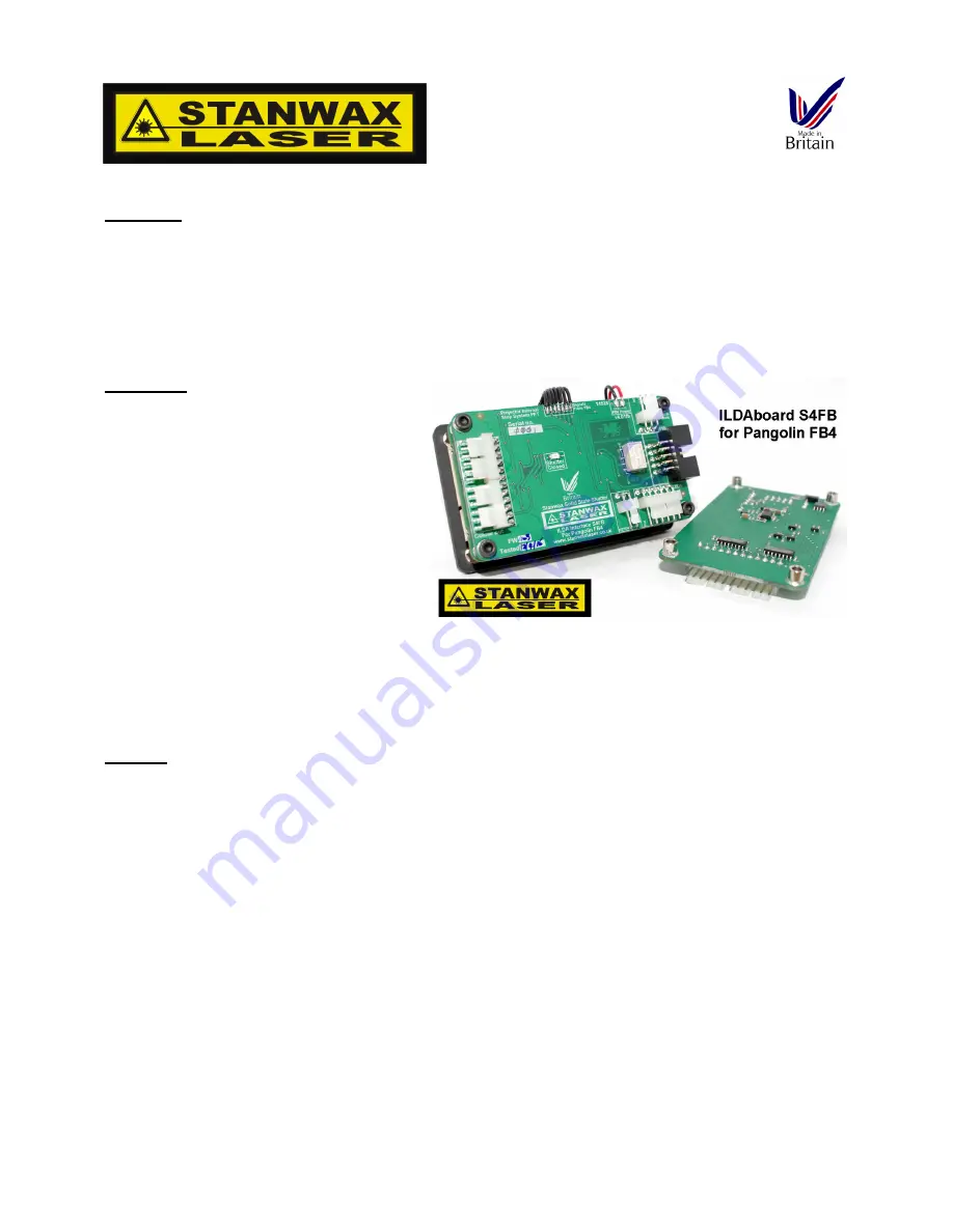
ILDA interface board S4FB
Revision 4.03FB June‘16
Introduction
The Stanwax Laser ILDA interface S4FB is designed to provide interlock and emergency stop functionality to a laser projector
fitted with Pangolins FB4 laser controller or to an FB4 fitted to a remote housing.The board contains safety interlock circuits,
that along with the ILDA shutter signal and emergency stop input, enable or disable the laser output. The safety interlocks
include a key switch (or other interlock circuit), plus e-stop and ILDA cable interlocks plus output is provided for a laser
emission LED to be located on the front of the projector. The remote interlock connection also has the facility to connect a
laser start button and a laser status LED that can be housed remotely with the e-stop plus there is facility for many projectors
equipped with this board (or any Stanwax ILDA board V1.03 onwards) to be operated by a single e-stop. All of these features
are designed to assist in making the projector comply with BS EN:60825-1:2007. Previous versions of this product have been
used in USA to achieve projector variance.
What’s New?
The latest development of our ILDA board uses an
electronic shutter to kill the laser output. Three
versions are available in total, This manual is for
S4FB for use with a Pangolin FB4. The S4i and S4p
versions are dealt with in a separate manual.
The S4FB version has been designed to neatly piggy
back on the rear of the FB4 as shown right. Power
fed to the ILDA board is passed on to the FB4 and
the colour signals from FB4 are fed to the ILDA board
where they pass through the solid state shutter which
is controlled by the e-stop and interlock circuits as
well as the shutter signal from the FB4. Unlike the
other versions S4i & S4p the scanner signals are not
handled by this board but should be used directly
from the FB4.
The most significant feature on the S4 version of our widely used ILDA board is the addition of *Stanwax Solid State Shutter
technology – hence the name S4. This provides a six channel electronic shutter that will kill laser output via the laser
modulation lines in <100uS. This has been developed and tested over a number of years so we are confident that you will
have the safest and most compliant laser projector yet with this system.
Despite all the changes, the interlock loop and reset circuit have been carried over from V1.xx so you can be certain of a
tried and tested emergency stop and interlock system. Additionally as with all S4 versions, a user programmable time delay
for projector start up (zero to 60 seconds) can be implemented.
* see section ‘S4 Technology’ for full explanation
Operation
The Ilda board has an on board timer chip that controls the solid state shutter to the lasers in the projector. This timer is held
in a hard reset condition when the interlock loop is broken or the emergency stop is tripped, thus preventing laser output.
The interlock circuit consists of a short circuit protected 12V feed which is routed, initially, through the key switch pins. As
well as providing a connection for a key switch, this port can provide connections to other interlocks, such as a case open
micro switch. (additional interlocks should be wired in series and set that they go open circuit when the projector needs to be
in a ‘safe condition’.) Following the key switch connector, the signal is presented to the remote interlock box header. This is
used with a short ribbon cable to present a 9 pin sub-d connector on the laser rear panel. To ensure a fail safe system the
connector used externally for the remote connector must link out to complete the continuous loop, as any break in it will
prevent the laser from operating.
The remote connector also provides connections for an emergency stop for use at the
laser control position, which must use contacts that close when the e-stop button is released. We recommend a ‘Key Only’
release for added security.
As the interlock loop and the E-stop circuit must be complete for the system to operate, any break in either will result in the
laser output ceasing. This would include disconnection or breaking of the cables to the E-stop or the interlock circuit,
providing a fail safe system.
Once the interlock circuit is complete the timer chip comes out of reset as indicated by the Bi-colour LED turning green. This
signifies that the projector is armed and ready to be activated. Closing momentary contacts between pins 5 & 7 on the 9-way
remote interlock connector will start a short time delay (this delay is factory set to 7 seconds but can be user set, for up to 60
seconds - see ‘user programmable timer’ section). As the time is elapsing the Bi-colour LED will flash red to green indicating
that the time sequence is in progress, before remaining red indicating that the time delay is complete. At this moment the
solid state shutter is opened allowing the laser sources to output, and the emission LED is provided with power.
Whenever the Bi-colour LED is lit static red, the laser is now fully active and laser emission is enabled. There are
connections on the 9-way remote interlock connector for this LED to be duplicated at a remote location, and an E-stop with
LED and start button can be used to provide all of the functionality you need at your control station.
If you do not need a start function (laser output is below class IV) then the start button pins can be joined on the rear of the
9-pin remote connector, and as soon as the interlocks are all made the time delay will begin.


