


Parts List, Fluid Section
30
3A4552A
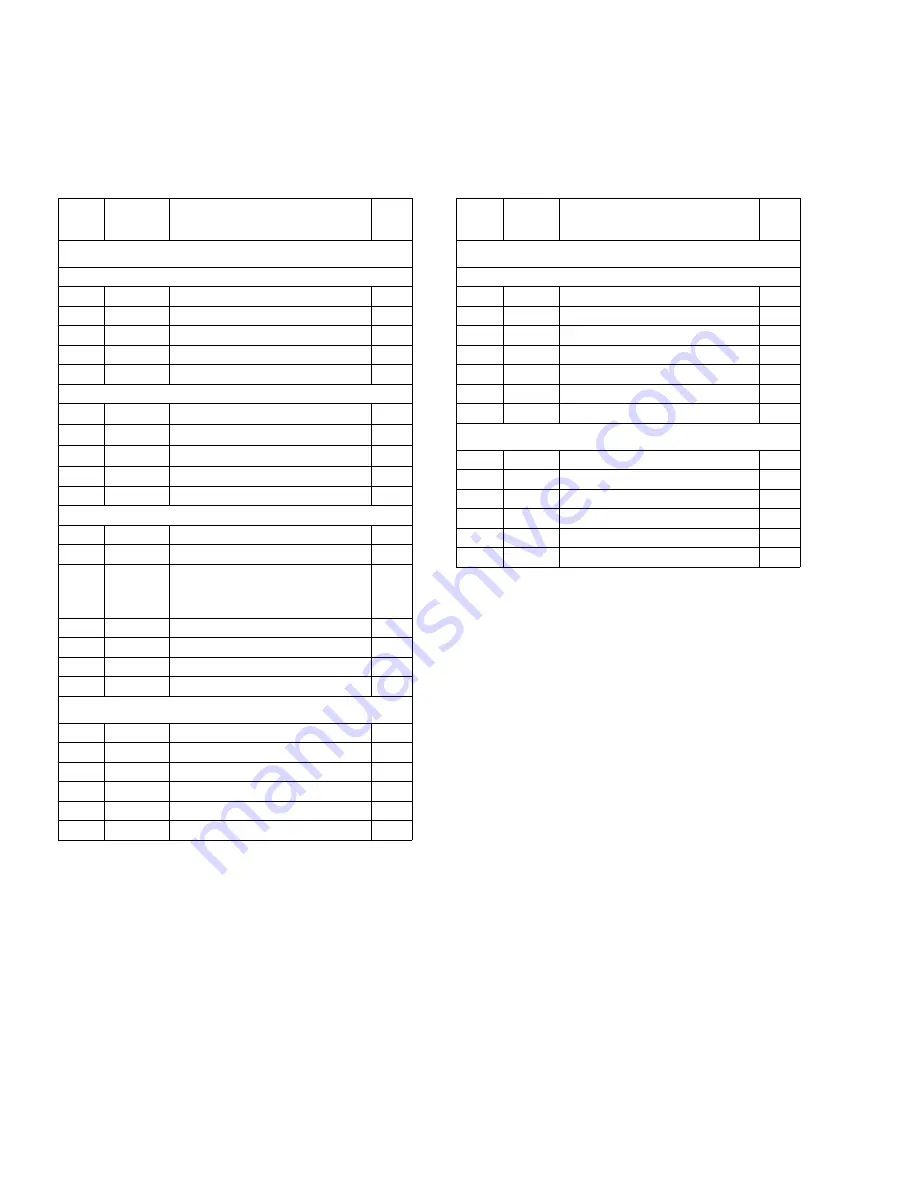
Parts List, Fluid Section
Pump Configuration
* Indicates replacement parts.
Inlet and Outlet
* Indicates replacement parts.
Ref.
No.
Part No. Description
Qty
Models SPXX30
3A Approved Ball Check Pump
132
400-308
CLAMP, 4 in.
4
2XB
400-319
SEAT
4
234
400-303
COVER, fluid
2
240*
400-322
GASKET, 4 in., EPDM
12
2XA
400-320
STOP, ball
4
Standard Ball Check Pump
132
400-334
CLAMP, 4 in.
4
233
400-313
SEAT
4
234
400-299
COVER, fluid
2
240*
400-322
GASKET, 4 in., EPDM
4
242*
400-315
GASKET, ball stop
4
Flapper Check Pump/Poultry Pump
234
400-299
COVER, fluid
2
240*
400-322
GASKET, 4 in., EPDM
12
200
400-333
MODULE, flapper;
includes 4x of items 132, 248,
251, 252, and 12x item 240
1
132
400-308
CLAMP, 4 in.
4
248
400-331
HOUSING, lower flapper
4
251
400-332
VALVE, flapper, weldment
4
252
400-314
HOUSING, upper flapper
4
Model SPSG15
132
400-273
CLAMP, 3 in.
4
2XB
400-323
SEAT
4
234
400-304
COVER, Fluid
2
240*
400-321
GASKET, 3 in., EPDM
12
2XA
400-324
STOP, Ball
4
135
400-318
CLAMP, sanitary, diaphragm
2
Ref.
No.
Part
No.
Description
Qty
Models SPXX30
Tri-clamp tee
128
400-300 ELBOW
4
129
400-321 GASKET, sanitary, EPDM, 3 in. 4
130
400-273 CLAMP, sanitary, 3 in.
4
132
400-308 CLAMP, sanitary, 4 in.
6
135
400-316 CLAMP, sanitary, diaphragm
2
331*
400-301 TEE, inlet, 3 in.
1
339*
400-301 TEE, outlet, 3 in.
1
Model SPSG15
128
400-306 ELBOW
4
129
400-325 GASKET, sanitary, EPDM, 2 in. 4
130
400-307 CLAMP, sanitary, 2 in.
4
132
400-273 CLAMP, sanitary, 3 in.
8
331*
400-305 TEE, Inlet, 2 in.
1
339*
400-305 TEE, Outlet, 2 in.
1