


7
Inspection and maintenance
44
01.2019
ba
-o
.1
.8
.0
-en
-3
.1
7.15
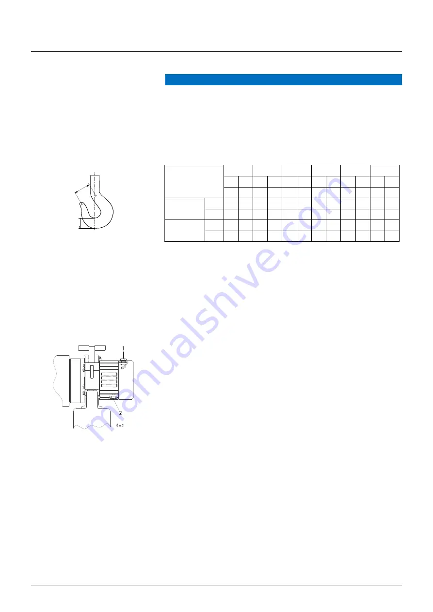
Checking hook for wear
NOTICE
Danger of material damage
The load hook, suspension hook and bottom hook block must be checked for damage
and wear. Deformations, cracks, cuts caused by impact and corrosion must be as-
sessed.
The hook safety latch must close completely, replace if necessary.
The damage can only be assessed by a qualified person.
•
The hook dimensions must not exceed those specified in the following table.
Fig. 53
ST05
ST10
ST20
ST30
ST32
ST50/ST60
1/1 2/1 1/1 2/1 1/1 2/1 1/1
2/1 1/1 2/1 1/1 2/1
[mm]
[mm]
[mm]
[mm]
[mm]
[mm]
Load hook
h
19
24
19
24
24
31
31
37
31
40
37
48
h min. 18
22.8 18
22.8 22.8 29.5 29.5 35.2 29.5 38
35.2 45.6
Suspension hook
h
24
24
24
24
37
37
37
37
39.5 39.5 39.5 39.5
h min. 22.8 22.8 22.8 22.8 35.1 35.1 35.1 35.1 37.5 37.5 37.5 37.5
y
new
see hook certificate
y
perm
=
1.1 x y
new
If value h
min
and/or y
perm
is reached → replace hook
•
If the load hook or suspension hook should display distortion, breaks, cracks or
corrosion they must be replaced.
7.16
Oil change
Fig. 54
•
Suspend chain hoist horizontally.
•
Change oil while warm if possible.
•
See "Technical data" for suitable types and quantity.
•
Replace copper gaskets.
•
Screw down oil drain plug (2) and oil filling plug (1) (25 Nm).
Dispose of used oil in accordance with environmental regulations.
h
y
W0973
Summary of Contents for ST05
Page 1: ...Chain Hoists Original instructions ...
Page 2: ......


