


Parameterization and Commissioning
26
253215 / 941960310090
2017-04-21·BA00·III·en·01
Bus-Carrier for linking device
Series 9419/0..-LD1-..E1
EN
EN
EN
EN
EN
EN
EN
EN
EN
EN
EN
EN
EN
EN
EN
EN
EN
EN
EN
EN
EN
EN
EN
EN
EN
Connection of the redundancy link interface (RDL)
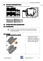
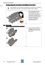
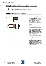
8.3.5 Connecting the bus-Carrier to the Equipotential Bonding
Connect the equipotential bonding/shield collective terminal to the earthing network to
establish equipotential bonding.
18039E00
8.3.6 Connecting the Diagnostics Communication Module (DCM)
9
Parameterization and Commissioning
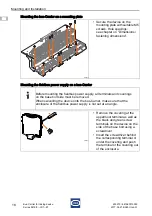
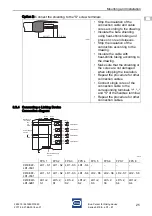
Connection of the auxiliary power:
Over the pac-Bus of the bus-Carrier when the linking device is connected.
Connection of the Ethernet ports:
Over RJ45 sleeves.
Connection of the FF-H1 bus:
By insertion onto the bus-Carrier.
18086E00
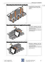
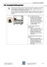
• In the case of a redundant bus-
Carrier 9419/04R-LD1-02E1,
connect the primary
linking device to the secondary
linking device over the
redundancy link interface
(RDL) (see the operating
instructions for the linking
device).
For information regarding the connection of the diagnostics communication
module (DCM) Type 9415, see corresponding operating instructions.
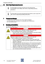
DANGER
Explosion hazard due to incorrect installation!
Non-compliance results in severe or fatal injuries.
• Check the device for proper installation before commissioning.
• Comply with national regulations.
6
5
4
6
5
4
RDL of primary Linking Device
RDL of secondary Linking Device
GND
GND
RX
TX
RX
TX
screen


