Function and Device Design
10
253215 / 941960310090
2017-04-21·BA00·III·en·01
Bus-Carrier for linking device
Series 9419/0..-LD1-..E1
EN
EN
EN
EN
EN
EN
EN
EN
EN
EN
EN
EN
EN
EN
EN
EN
EN
EN
EN
EN
EN
EN
EN
EN
EN
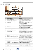
4.2
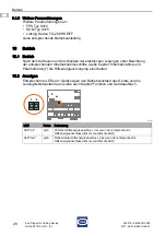
Device Design
18042E00
#
Device component
Description
1
2 x fault message contact
PF (5/6): Power fail, dia (7/8): Diagnostics
2
2 x auxiliary power connection (24 V)
pri (1/2): primary auxiliary power connection
red (3/4): redundant auxiliary power connection
(optional use)
3
2 x DIP switch
RED: Monitoring of redundant auxiliary power
supply activated/deactivated
DIA: Diagnostics/error contact
activated/deactivated
(see the Chapter "DIP switch on the bus-Carrier")
4
2 x LED green
Auxiliary power supply operation indication
(one LED per auxiliary power connection)
("pri" = primary or "red" = redundant)
5
3-pole connection terminals
Connection of the fieldbus segments for field
devices (trunk connection)
6
Shield bus for clamping bracket
(accessory parts)
Shield support for the segment line
(clamping bracket available as accessory 113509).
Optionally, the shielding for the segment line can
be connected to the "S" shield terminal of the
fieldbus terminal.
7
Equipotential bonding/shield collective
terminal
Equipotential bonding/shield: Shared connection
point of shield bus and "S" shield terminals
8
Slots for the linking device on pac-Bus
Transmission of the external auxiliary power to the
linking device and connection for the respective
segments over the carrier
9
Base bolt
Click-in mechanism on the DIN rail
(1 or 2 base bolts depending on the version)
10
Slot for fieldbus power supply of type 9412
on pac-Bus
(Segment 1 on the left to Segment 4/8 on
the right)
Transmission of the external auxiliary power to the
individual fieldbus power supplies and supplying
the respective segment over the carrier
11
DCM connection
Ribbon cable connection for module Type 9415
12
Slot for diagnostics communication module
(DCM)
Transmission of the diagnostics data of the
segments over a separate fieldbus segment

