Obsolete Product(s) - Obsolete Product(s)
UM0579
Artwork prints
31/37
Appendix C
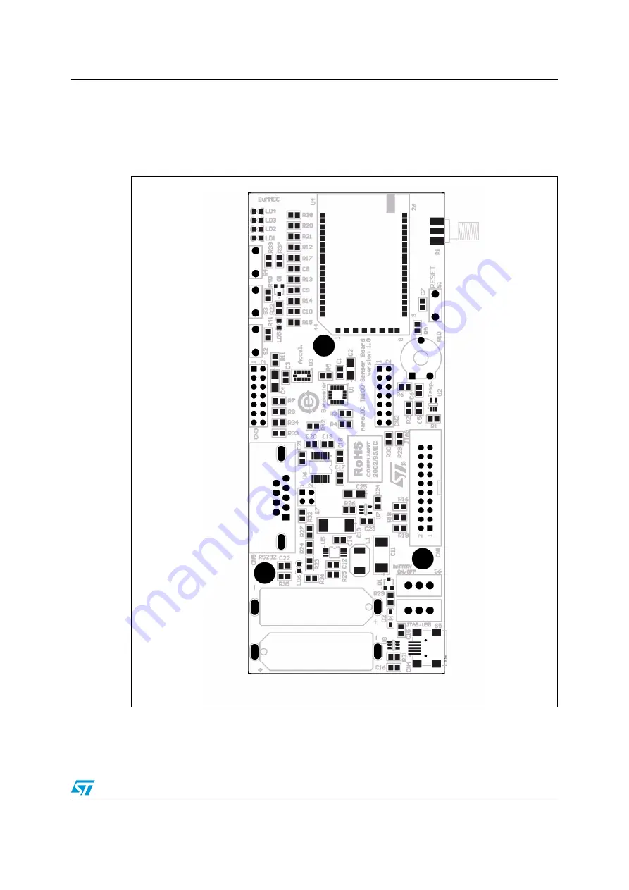
This section shows the layout of the evaluation board PCB (top and bottom layers).
Figure 28.
Evaluation board PCB (top layer)
Page 1: ...ED LD5 power supply LED LD6 The sensor boards act as source of information providing data regarding distance measurement ranging temperature accelerations and status The software consists of The ST TN...
Page 2: ...nnector CN2 9 3 1 3 Extension connector CN3 10 3 1 4 USB connector CN4 10 3 1 5 RS 232 connector CN5 11 3 2 General purpose and reset buttons 12 3 3 LED indicators 13 3 4 Power supply 14 4 Getting sta...
Page 3: ...using HyperTerminal 24 5 2 Upload firmware using TN100 application 25 5 3 Loading the boot loader into the sensor board 26 Appendix A Board assembly setup manual 27 Appendix B Bill of materials 29 App...
Page 4: ...Q The Automatic Repeat Request ARQ scheme is used to achieve correct data transmission CSMA CA Carrier Sense Multiple Access with Collision Avoidance CSS Chirp Spread Spectrum FEC The Forward Error Co...
Page 5: ...ting in the 2 45 GHz ISM band with extremely low power consumption over a wide range of operating temperatures The TN100 supports 7 frequency channels with 3 non overlapping channels This provides sup...
Page 6: ...ate the ST TN100 technology and hence perform remote ranging operations between nodes sending and receiving simple data packets and text messages getting sensor values and setting the status of on boa...
Page 7: ...rates with the firmware running on the sensor nodes and it is able to Get specific parameters such as MAC address channel FEC MAC retries and so on for each sensor node Get sensor data for each sensor...
Page 8: ...N2 CN3 for connecting different hooks on extensions Power supply options 5 V from JTAG J Link USB 5 V VBUS NiMH batteries On board step up converter and linear regulator 2 5 V One reset S1 and three g...
Page 9: ...feature at http www segger com Figure 5 JTAG connector pinout 3 1 2 Extension connector CN2 The 14 pin extension connector CN2 can be used together with the CN3 connector to connect an extension The C...
Page 10: ...SB AB SMT connector The communication lines are not used with the TN100 board The VBUS 5 V voltage pin 1 can be used as an alternative board power supply Figure 8 USB connector CN4 pinout Table 3 Exte...
Page 11: ...own in Figure 9 For correct interconnection with a PC a direct cable should be used Figure 9 RS 232 connector CN5 pinout Figure 10 Switch S7 RS 232 lines TX RX cross or direct cable selection Table 5...
Page 12: ...ed schematics are in Table 8 Table 7 RS 232 lines TX and RX cross or direct cable selection RS 232 cable selection Jumper selection Crossed Direct AM00267 2 4 1 3 AM00268 2 4 1 3 Table 8 General purpo...
Page 13: ...the board LD6 indicates the presence of an external 5 V power supply either from the USB or from the JTAG connection When LD6 is off the board is powered from batteries to reduce the overall power co...
Page 14: ...TM32 pin Function LEDs schematic LD1 PB15 General purpose LD2 PB13 General purpose LD3 PB11 General purpose LD4 PB10 General purpose LD5 X TX RX activity LD6 X External source voltage supply indicatio...
Page 15: ...GND Table 11 CN1 pins description Pin Signal 19 5 V 2 20 GND all even pins Table 12 Batteries 2 x 1 2 V NiMH 1 1 Default assembly BAT3 battery holder Component Signal BAT1 BAT2 Soldered directly to PC...
Page 16: ...l entry to display the TN100 Application window 4 1 2 Board setup Each board is provided with a set of batteries and preloaded firmware Boards can be powered using the USB connection through CN4 conne...
Page 17: ...us It is worth to say that up to now all the data are gathered from the serial cable 5 Switch on the other sensor board the Sensor1 This time the sensor board will be detected through RF by the Gatewa...
Page 18: ...in the Sensing and Control view The MEMS entry in particular requires to be expanded further to read the X Y and Z values The TN100 Application also controls the status via RF of on board items such a...
Page 19: ...re 17 Figure 17 Restarting a node 4 2 4 Ranging One of the more interesting features that may be experimented with is the execution of Ranging operations that is being able to get an approximation of...
Page 20: ...sion The Current m box shows the value of the current measured distance If the Average On Samples field is higher than 1 that value will be the calculated average on the field content At the end the l...
Page 21: ...fault value is 16 and the unit of measure is bytes 4 Edit the Packet field to set the number of packet s you wish to send Default value is 1 5 Edit the Delay field to set the delay inserted between th...
Page 22: ...d box For example Hello 4 Click Send Message to send the message to the selected receiver The Message received box will show a string like if the Gateway and Sensor1 were selected as transmitter and r...
Page 23: ...ng to the following fields ID is a numeric identifier associated to the transmitted packets Time is the number of seconds passed since the application start Type is the packet type R means the packet...
Page 24: ...ause unexpected behavior could result otherwise 5 1 Upload firmware using HyperTerminal To upload a new firmware version using the HyperTerminal follow the steps below 1 Make sure the sensor board is...
Page 25: ...eway is connected by the serial cable to the host PC and each board has to become a Gateway only once just for the time required to download the firmware To upload a new firmware version using the TN1...
Page 26: ...t loader is present or not please do the following 1 Keep button S2 pressed and reset the board via button S1 2 LEDs LD2 LD3 and LD4 should now blink as confirmation that the boot loader is present an...
Page 27: ...rposes R30 0 Connects PA2 MCU pin to the batteries The battery voltage can be measured if PA2 is configured as ADC input line PA2 MCU pin is disconnected from the batteries and can be freely used for...
Page 28: ...y used for other purposes R9 0 Connects potentiometer output pin to the PA1 MCU pin which can be configured as ADC input PA1 MCU pin is disconnected from the Potentiometer output pin and can be freely...
Page 29: ...al 6 3 V A GM CTS2M2 6 3 V Yes CN1 GM MLW20G GM MLW20G Farnell 1247390 SPC Technology SPC20508 Yes CN2 CN3 Header 2X7 GM S2G14 Farnell 1319205 Molex 10897141 Yes CN4 USB MINI B F SMD Molex socket USB...
Page 30: ...ide switch GM P B143 Farnell 1197660 Tyco SLS121PCFN Yes S6 Slide switch GM P B143 Farnell 1197660 Tyco SLS121PCFN Yes S7 Header 2X2 GM S2G4 Farnell 1278358 Molex 10 89 7082 Yes U1 Barometer LGA16 ST...
Page 31: ...te Product s Obsolete Product s UM0579 Artwork prints 31 37 Appendix C Artwork prints This section shows the layout of the evaluation board PCB top and bottom layers Figure 28 Evaluation board PCB top...
Page 32: ...Obsolete Product s Obsolete Product s Artwork prints UM0579 32 37 Figure 29 Evaluation board PCB bottom layer...
Page 33: ...G 2 5 V JTRST JTDI JTMS JTCK JRTCK JTDO NRST DBGRQ DBGACK 2 5 V R16 10 K R18 10 K R19 10 K JTAG JTDI JTMS JTCK JTDO NRST 2 5 V P1 SMA C7 100 nF S1 GM DT2112C NRST 1 2 LD3 yellow 1 2 LD4 red R20 470 R2...
Page 34: ...K C12 100 nF R29 120 R26 NC R27 0 R25 180 k Power supply PA2 R30 0 PA3 R28 0 S6 SW SPST D2 ST STPS0520Z V BUS 1 D 2 D 3 NC 4 GND 5 SHLD 6 SHLD 7 SHLD 8 SHLD 9 CN4 GM USB MINI B F SMD BAT 2 GM B N360 2...
Page 35: ...rved 3 V DD _IO 4 GND 5 Reserve d 6 Reserve d 7 GND 8 Reserved 9 INT2 10 RDY INT1 11 SDA SDI SDO 13 SA0 SDO 12 GND 14 SCL SPC 15 CS 16 U1 ST LPS004DL 2V5_P I2C1_SDA I2C1_SCL Pressure_Int1 Pressure_Int...
Page 36: ...Obsolete Product s Obsolete Product s Revision history UM0579 36 37 Revision history Table 16 Document revision history Date Revision Changes 21 Jan 2009 1 Initial release...
Page 37: ...ATION IMPLIED WARRANTIES OF MERCHANTABILITY FITNESS FOR A PARTICULAR PURPOSE AND THEIR EQUIVALENTS UNDER THE LAWS OF ANY JURISDICTION OR INFRINGEMENT OF ANY PATENT COPYRIGHT OR OTHER INTELLECTUAL PROP...