Note:
The PFC calibration has to be performed for a given design (based on the component choice, supply output
power, etc.). It is not necessary to perform the calibration for each unit created.
11.3
PFC protection
During the PFC calibration, the normal algorithm behavior is changed. In particular, the PFC mode change
algorithms can be disabled to adjust some parameters.
Danger:
Consequently, the PFC bulk voltage can rise above the nominal voltage at light load, leading to
component (e.g. Bulk capacitors, MOS) damage and even destruction.
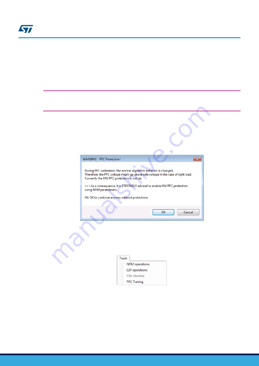
To prevent any damage, the GUI performs a preliminary safety check by reading the NVM content and checking if
the PFC hardware protection is set. If not, a warning is displayed (as shown in the figure below), inviting the user
to update NVM accordingly.
Important:
You can override the warning, but it is under your own responsibility.
Figure 35.
PFC protection warning window
11.4
Step by step calibration example
To start calibration, go to the
Tools
menu and select
PFC tuning
. The following window pops up.
Figure 36.
PFC tuning menu
Note:
To perform the calibration, the GUI has to communicate with the
. Since the UART communication is
disabled by default in running mode, a special procedure (similar to the ATE mode) is applied to enable UART
communication, which requires switching the power supply on/off, as prompted by the GUI.
As previously mentioned, during the tuning operation phases, the GUI modifies the RAM parameters but writes
nothing in NVM (so, changes are not persistent).
UM2342
PFC protection
UM2342
-
Rev 1
page 32/57


