


SS-15 BRI (ISDN 2 GSM) USER MANUAL
DOC. NO: SS-15-14 (REV. 01)
Page 14 of 26
4.9
PINOUT FOR THE CONNECTORS
The SS-15 BRI (ISDN 2 GSM) features four
data connectors at the bottom of its case. All
connectors are of the same type, female RJ-
45, but they have different functions. Please
read the paragraph carefully and perform the
connections accordingly.
Serial connector
For programming the SS-15 BRI (ISDN 2 GSM) the special connection cable
must be used. The special serial cable is included in the package of the SS-
15 BRI (ISDN 2 GSM) equipment.
The end towards the SS-15 BRI features an RJ11 connector while the end
towards the COM port of the computer features a standard female DB-9
connector.
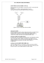
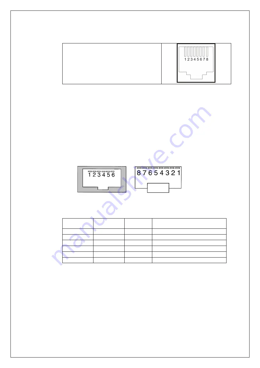
In the drawing below the pin numbering can be seen (from left to right) of the
RJ11 female connector of the SS-15 BRI and the corresponding male RJ11
male connector on the serial programming cable.
Figure 8.Serial connector
See table below for pinout of cable and its connectors.
RJ11
Symbol
DB-9
Signal
1
DSR
6
Data Set Ready, input
2
RxD
3
Receive Data, input
3
GND
5
Signal Ground
4
TxD
2
Transmit Data, output
5
DTR
4
Data Terminal Ready, input
6
CTS
8
Clear To Send, input
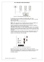
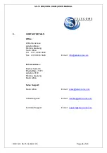
TE connector – used for connecting the SS-15 BRI TE interface.
The TE interface of the SS-15 BRI (ISDN 2 GSM) unit is used for connection
to NT interfaces of the ISDN private branch exchange or of the ISDN public
telephony network. TE interfaces are provided with embedded termination
resistors. These resistors may be enabled by means of corresponding
jumpers, the pair JAT1 and JAT2.