2.2 Front Panel Control
29
2.2.3.2 Edge
When using
Ext Sync
to control the chopper, the control unit can trigger
on the following edges:
Rising TTL
Falling TTL
Sine
Use the
Edge
button to select from the three available edge types. The
button scrolls through the options from top‑to‑bottom.
It is generally advantageous to provide rectangular‑wave TTL signals
to the Ext Sync input, as a sharp edge is less corruptible by noise than
a slowly ramping sinusoid (especially for input frequencies less than
1 kHz). Furthermore, the Source Clock will experience a frequency‑ and
amplitude‑dependent phase shift relative to a sinusoidal input signal
due to the circuitry responsible for
edge detection.
Edge selection has no impact when
Source
is not set to
Ext Sync
. The
edge indicator LEDs will turn off, and the
Edge
button will be de‑
activated.
2.2.3.3
Multiplier
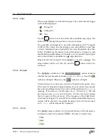
The
Multiplier
sub‑block of the
CONFIGURATION
section indicates
whether the user has selected either
𝑛
or
𝑚 ≠ 1
. If
𝑛 = 𝑚
, then the
×
1
indicator will light. Otherwise, the
×
n
m
indicator will light.
Certain choices of
𝑛
and
𝑚
may result in a Maximum Frequency error.
If the motor is already running (therefore the slot counts have already
been surveyed) illegal values for
𝑛
and
𝑚
will be rejected with a
Prohib
message. If the motor is off, all values of
𝑛 ≤ 200
and
𝑚 ≤ 200
will
be accepted, since
𝑛
slots
is not yet known. On the next motor startup
the slot counts will be surveyed. If the frequency of the Shaft Refer‑
ence Clock (see Figure 2.1) exceeds the maximum permissible frequency,
startup will be aborted, a maximum frequency error will be recorded,
and
FrqErr
will be temporarily displayed.
2.2.3.4
Control
The
Control
target indicates which periodic feature will be frequency‑
and phase‑locked to the selected
Source
. The user can select from:
Shaft
Inner
Outer
SR542 Precision Optical Chopper


