SPIDAR Software
40
For example, at 25 km/h, you are moving 6.94m per second. If the GPS has 1.00 second
latency, your data position would be off by 6.94m. Details on calculating GPS Latency
can be found in
. The latency will be saved in the data for use in
EKKO_Project. It could also be adjusted at that time, if it’s unknown at the time of
acquisition.
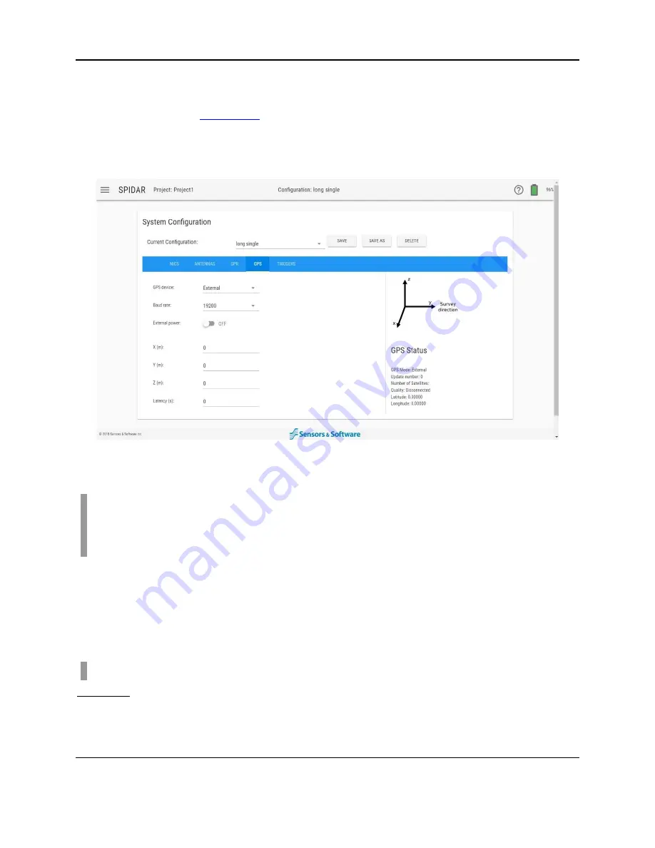
Figure 4-21: Setting options under the GPS tab
Note
: In a daisy-chained configuration, GPS data is only recorded on the Master NIC-500.
For the subordinate NIC-500s, the user must copy the .GP2 files from the Master NIC-500
and rename them to match the subordinate NIC-500(s). Then the appropriate GPS offset
must be applied in the EKKO_Project software (see the EKKO_Project manual for details).
4.3.5
Triggers
A trigger is used to fire, or pulse, the GPR system to collect a trace of data. There are three
ways to trigger the GPR system: using an Odometer, Manually or Free Run mode. These are
set by selecting Trigger method and configuring the appropriate settings.
Note
: If there are multiple NIC-500s, the same Trigger Method must be used for all of them.
Odometer
Used most often if the configuration has a wheel encoder. When the odometer wheel moves
one step size, it will cause the transmitter to fire. This is the easiest mode to operate in, as you
don’t have to worry about collecting data at equally spaced intervals.
Summary of Contents for SPIDAR NIC-500s
Page 1: ......
Page 2: ...ii...
Page 4: ...Warranty Confirmation iv...
Page 6: ...vi...
Page 10: ...Introduction 2...
Page 28: ...Getting Started 20...
Page 66: ...SPIDAR Software 58...
Page 78: ...SPIDAR SDK 70...
Page 88: ...Compatibility 80...
Page 90: ...Technical Specifications 82...
Page 102: ...Appendix D GPR Knowledge 94...
Page 106: ...Appendix F Health Safety Certification 98...
Page 114: ...Appendix G GPR Emissions Interference and Regulations 106...
Page 116: ...Appendix H Instrument Interference 108...
Page 118: ...Appendix I Safety around Explosive Devices 110...


