background image


C550c Operation Manual 

6 Operating the system 


www.cuesinc.com


175


6.10 Zero the camera distance 

Your survey needs to accurately record the distance of the camera from the starting manhole. This 
ensures that pipe defects can be accurately located. However, in most cases you will need to unwind the 
pushrod some distance so you can deploy the camera down into a manhole before starting the survey.  

To ensure accurate camera distances are recorded in your survey videos and observations, you need to 
zero the camera distance when the camera is in position (typically in the center of a manhole) before you 
start the survey.  


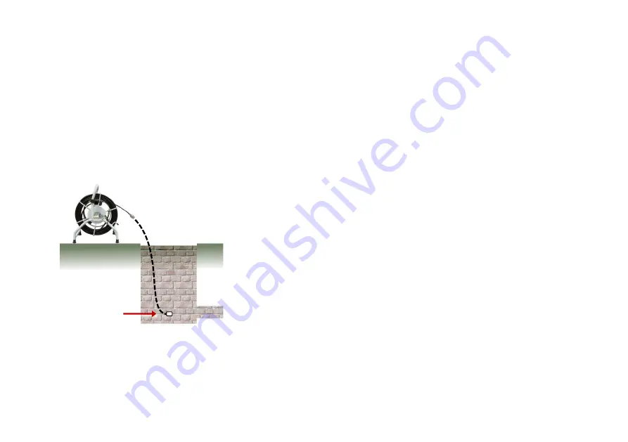
Fig. 6-20: Zeroing the camera position. 

1

 Zero the camera position when the camera is here. 

Note: This task is also called 

‘zero distance’ and ‘zeroing the rod counter’. Do not confuse this task with 

zero calibration of the reel. See the definitions in 

page 22

. 

Summary of Contents for CUES flexitrax C550c

Page 1: ...flexitrax C550c Operation Manual CUES advanced crawler based digital video inspection system Operation Manual C550c OPMAN ENG 08 Rev 08 May 2021 ...

Page 2: ...re purchasing the appropriate product for your needs The contents of this manual are subject to change CUES products are under continuous development CUES reserves the right to modify any product including this manual without notice and some product changes may have taken place after publication of this manual For the latest information about the flexiprobe product family including all accessories...

Page 3: ...o alter or amend any published specification without notice This document may not be copied reproduced transmitted modified or used in whole or in part without the prior written consent of CUES Inc Other trademarks or registered trademarks mentioned in this document belong to their respective owners Disclaimer Any third party products including hardware software and services mentioned in this manu...

Page 4: ...WEEE Directive 2012 19 EU Industry Canada Compliance ICES 003 Class A Notice This Class A digital apparatus complies with Canadian ICES 003 Avis NMB 003 Classe A Cet appareil numérique de la classe A est conforme à la norme NMB 003 du Canada Ingress Protection Marking This system complies with this rating for IEC standard 60529 solid particle and liquid ingress protection IP55 Controller covers an...

Page 5: ...imits are designed to provide reasonable protection against harmful interference when the equipment is operated in a commercial environment This equipment generates uses and can radiate radio frequency energy and if not installed and used in accordance with the manufacturer s instruction manual may cause harmful interference with radio communications Operation of this equipment in a residential ar...

Page 6: ...ons alert you to possible equipment damage Note Notes contain useful information Warning symbols General Warning Refer to the manual for specific instruction or advice Electrical Hazard Observe safe practices and exercise extreme caution Biohazard Disinfect after use Wear appropriate personal protective equipment PPE Hot Surface Allow to cool or use appropriate protection when handling Heavy objec...

Page 7: ...ork as it may identify other safety issues Always follow standard safety precautions for working in hostile environments including precautions for manual handling biological hazards and personal injury The C550c PSU has a number of ventilation slots around the casing that are designed to maximize air circulation and reduce heat There is a potential fire risk if the build up of heat is prevented fr...

Page 8: ...nsure that cabling is properly connected Always switch the system on and off using the controller power button and the on off switch on the Power Supply Unit PSU The PSU is integrated within the Powered Drum see page 37 and separate from the Manual Drum see page 38 Make sure that video and power cables are not entangled in the drum or reel Cable ties are recommended and will not impede system perf...

Page 9: ...nvironment If using a generator follow the manufacturer s instructions on load connection and sequencing In the absence of these instructions the following guidelines should be used When starting the generator ensure that all electrical loads including the flexitrax C550c are switched off before starting the generator Allow the generator to stabilize before connecting any electrical loads or switc...

Page 10: ...ear appropriate personal protective equipment PPE when handling the C550c Always use heavy duty industrial gloves when withdrawing a rod from a sewer Battery precautions The controller contains a Li Ion rechargeable battery Only use charging equipment provided by CUES The use of alternative chargers may cause a safety hazard and or reduce the life of the battery The battery is designed to protect ...

Page 11: ...Ion batteries must be disposed of properly use an approved recycling facility for electronic waste Camera precautions Warning The camera will get hot with use This is normal To avoid risk of burns do not touch the camera when it is switched on or immediately after switching it off Leave time for it to cool before handling Exercise care when handling the camera consider using gloves Warning The cam...

Page 12: ... available use the wheels to assist transport Observe heavy lifting safety practices when lifting any component of this system For the system weight and dimensions see the specifications on page 271 Warning Never lower crawlers or other heavy equipment into manholes while personnel work in the manhole Warning Always remove the fuse when the controller is transported by air Disposal Do not dispose ...

Page 13: ... 4 Warnings Cautions and Notes 6 Perform a risk assessment 7 Safety precautions 8 Disposal 12 Contents 13 1 Introduction 20 1 1 C550c features 21 1 2 Definitions 22 1 3 Safety notices 22 1 4 Training 23 1 5 Updates and latest information 23 1 6 CUES technical support 23 2 Quick Start 24 3 System overview 26 3 1 Controller 26 3 2 Controller home screen 34 3 3 Controller battery 36 ...

Page 14: ...inc com 14 3 4 Cable drums 37 3 5 Pushrod reels 44 4 System assembly 49 4 1 Crawler Camera and accessories 49 4 2 Drums External PSU 69 4 3 Command module 70 4 4 Controller 73 4 5 Pushrod reels 76 4 6 Cameras and accessories 78 4 7 Battery 87 ...

Page 15: ...t controller preferences and company details 95 5 4 Calibrate the equipment 99 5 5 Status icons 100 5 6 Configure the system settings 101 5 7 Import a company logo 134 5 8 Set up a video title page 135 6 Operating the system 141 6 1 Before you begin 141 6 2 Confirming the system equipment 142 6 3 Emergency stop 143 6 4 Crawler Deployment 143 ...

Page 16: ...m stop 155 6 6 Driving the crawlers 156 6 7 Camera control lights focus pan rotate zoom 166 6 8 Pushrod reels 171 6 9 Deploy pushrods 174 6 10 Zero the camera distance 175 6 11 Streaming images to a nearby device 177 6 12 Record a video 180 6 13 Video tools 193 ...

Page 17: ...4 Replay a video 202 6 15 Take a photo directly 204 6 16 Turn off the camera 207 6 17 Retrieve the crawler 208 7 Surveys 209 7 1 Create a new survey 209 7 2 Edit survey screen 212 7 3 Manage existing surveys 213 7 4 Export a survey 218 7 5 Observations 232 ...

Page 18: ...cons 263 10 Maintenance and cleaning 264 10 1 Maintenance 264 10 2 Cleaning the system 267 10 3 Factory reset 268 11 Software updates 269 12 Specifications 271 12 1 Controller specifications 271 12 2 Drums and PSU 273 12 3 Crawlers 274 12 4 Elevators 275 12 5 Lighthead 276 12 6 Crawler cameras 276 12 7 Crawler wheels and spacers 277 12 8 Controller to drum PSU link cables 278 12 9 Crawler wheel el...

Page 19: ...C550c Operation Manual Contents www cuesinc com 19 12 11 Pushrod reel and rod specifications 282 12 12 Pushrod camera specifications 283 13 Open Source Software 284 14 Index 285 Contact us 292 ...

Page 20: ...t is easy to transport and deploy enabling quick and successful inspections The C550c controller can drive any combination of compatible pushrod reels and cameras Its 12 1 307mm screen displays the camera s video feed stored videos and photos and configuration settings You operate the controller using its built in buttons and keyboard If required you can connect the controller to external video eq...

Page 21: ...ports videos and observation photos can be exported to USB memory sticks sent as email attachments or uploaded to Dropbox MSCC3 through MSCC5 survey standards are supported Surveys can also be performed using the integrated WinCan option subject to additional licensing Modular system fully compatible with any combination of flexitrax C550c drums crawlers and cameras and is also compatible with fle...

Page 22: ... position before you start the survey See page 175 where this is described for pushrod systems and the same principle applies for crawler systems Setting a zero distance is also known as zeroing the cable or rod counter Crawler and tractor both these terms are used in this document to refer to the motorized wheeled vehicle that is used to transport a camera 1 3 Safety notices Caution must be taken...

Page 23: ... accidents how to diagnose and repair simple issues as well as facilitating longer product lifetimes For more information go to www cuesinc com or contact your local CUES representative 1 5 Updates and latest information CUES may have released new system software user documentation or other information after you purchased your system You can download the latest software documentation and applicati...

Page 24: ...oth powered off Note This Quick Start section assumes that the controller battery is charged For details about charging the battery see page 87 2 Set up the controller a Optional Mount the controller onto the drum using the supplied clamp b Connect the drum to the controller using the link cable item 4 on page 31 c Connect the drum to the down hole equipment relevant to the survey required 3 Turn ...

Page 25: ...ed to the controller then press Select Otherwise change the equipment as necessary highlight Continue then press Select For full details about these steps see page 142 4 Deploy the crawler and camera into the pipe as required 5 Zero the camera distance as required using the 0 00 button For details see page 147 6 Create a survey and start recording your survey video For details see page 209 ...

Page 26: ...screen Video pictures and inspection reports are stored on a high speed high capacity 128GB internal solid state storage The C550c controller is compatible with the full range of C550c drums crawlers cameras and accessories as well as the full range of C540c cameras reels and accessories providing unmatched modularity and inspection capability from 1 30mm pipes all the way to 59 1 5m The C550c con...

Page 27: ...7 Controller front view Fig 3 1 Controller front view 1 On Off button Switches power ON or OFF When the system is powered on the on power indicator on the handle lights up 2 Buttons Allow you to navigate screen menus and control the system 4 1 2 5 7 6 3 2 8 8 ...

Page 28: ...the controller s WiFi Power and Battery Charge status see page 30 5 Panel buttons Allow you to record and play survey videos make observations and take photos mute the microphone turn the camera sonde on and off and zero the camera distance see page 33 6 Display LCD screen shows video still images and system information 7 Keyboard Use for text entry when setting up surveys and configuring the cont...

Page 29: ...e back and front of the handle LEDs indicate the controller s WiFi Power and Battery Charge status See page 30 2 Main connection panel Includes a socket for the link cable to the pushrod reel an external video input and Ethernet connection and the power socket See page 31 3 Auxiliary connection panel Includes an HDMI output dual USB ports and a battery fuse See page 32 4 Controller support clamp F...

Page 30: ...troller can detect available WiFi networks It does not indicate that the controller is connected to the internet 2 Power Lights up when the controller is powered on green 3 Battery charge Lights up while battery charging is underway amber When the battery is fully charged the LED changes to green Note Also indicates the controller is connected to an external power supply mains or vehicle 4 Battery...

Page 31: ... DC power input from mains supply or vehicle supply Warning Use only the supplied battery chargers mains or optional vehicle 2 Video input An RCA video jack provides an input from external video equipment optional 3 Ethernet port Used for remote control operations connections to an external WiFi access point etc 4 Socket for link to cable drum Connects the controller to the crawler mounted camera ...

Page 32: ...utput Allows you to display live video on an external monitor Video replay on an external monitor is not currently supported 2 For manufacturer use only 3 USB sockets Allows you to connect a USB memory stick or external keyboard 4 Fuse holder For a 5A MINI Blade fuse The fuse is suppled separately with the controller you must insert the fuse before operating the controller Warning You must remove ...

Page 33: ...Zero the camera distance See page 147 for details 3 Sonde LED Green when active 4 Mute microphone LED is red when microphone or headset is muted 5 Recording LED Red when video recording in progress 6 Record pause Press to start or pause video recording 7 Play pause Press to play or pause video playback 8 Stop Press to stop video playback or recording 9 Camera Press to take photo and make an observ...

Page 34: ...system settings and rotate the video feed It also shows real time system information crawler distance since being zeroed see page 175 and the Mimic see page 164 for information provided by this graphic If required you can overlay these details in your survey videos and observation photos Fig 3 7 Controller home screen A Button labels hidden B Button labels shown See next page for descriptions 1 2 ...

Page 35: ... Survey title 6 Menu button Shows or hides button labels 7 Settings button Opens the system menus 8 Set distance button Press to zero the camera distance for a new survey 9 Joint scan button Press for Cameras with Tilt function to perform a joint scan For other cameras press to rotate the video feed on the screen clockwise 9a or anticlockwise 9b 10 Recording and mic status 11 Free disk space GB Sh...

Page 36: ...charge above 90 This will dramatically increase the number of charge and discharge cycles that the battery can achieve Only charge your battery at temperatures of 10 40 C 50 104 F See below for more details Keep the power socket clean and dry at all times Keep the main connection panel closed when the controller is not in use See the image on page 29 Temperature Battery life is affected by the tem...

Page 37: ...a powered or manual drum that can accommodate cable lengths of 330 100m 495 150m 660 200m 820 250m and 1000 305m The powered drum contains an integral power supply whilst the manual drum requires an external power supply unit PSU The cable drum cassette in the powered drum is user replaceable Refer to the Appendix for instructions on how to remove and install the cable drum cassette Please contact...

Page 38: ...c com 38 Powered drum Fig 3 8 Powered drum including integrated PSU showing how the command module is mounted 1 Command module support stand 2 System on off switch Note the C550c controller has a separate on off switch 3 Command module 1 3 4 5 5 5 6 11 ...

Page 39: ...nstantly shuts off system power When initiated the system must be reset 7 Pushrod connector Connect and power compatible 540 pushrod systems to your C550c controller 8 Pendant Controller connector for joystick button control of system 9 Command module connector To connect the command module link cable 10 Power on off indicator A White LED lights up when the PSU is switched on and powered up 11 Pow...

Page 40: ...C550c Operation Manual 3 System overview www cuesinc com 40 Manual drum and PSU 13 Cable drum Houses up to 305m 1000 of cable 14 Cable brake ...

Page 41: ...erview www cuesinc com 41 15 Crank handle socket 16 Command module support clamp 17 PSU link cable socket 18 Manual layering handle To assist with laying cable evenly on the drum 19 Cable rollers 20 Link cable connection for manual drum ...

Page 42: ...6 diameter Fig 3 9 P354 crawler with Forward View camera installed and P356 crawler with pan tilt and zoom camera large elevator and lighthead installed Both crawlers are compatible with a choice of three color cameras The P550 CAM FW is a fixed forward view camera The P550 CAM PT offers pan and tilt and the P550 CAM PTZ offers pan tilt and 10x optical zoom ...

Page 43: ...offer automatic TILT protection By default this will halt the crawler in hazardous tilting situations when its roll first exceeds 35 The user will be shown a tilt hazard warning and can restart the crawler movement if necessary The user can change this behavior to warn only without stopping the crawler or can disable the warning altogether ...

Page 44: ...eel or coiler holds the pushrod and camera on a revolving drum The C550c system supports the reels below See page 275 for reel specifications Fig 3 11 C550c pushrod reels 1 543c reel 2 542c reels available in two lengths 3 541c reels standard reel and extra flexible Plumbers reel 1 2 2 3 3 ...

Page 45: ... reel type 2 Stowage hooks Use for storing the link cable on the pushrod reel 3 Link cable socket Connects the link cable to the reel 4 Brake Not shown Located on reverse side of reel Adjustable to control the movement of the reel or to lock it 5 Pushrod guide Guides the rod on and off the reel Must be kept clean 6 Adaptor clamp Allows the controller to be mounted onto the pushrod reel 1 5 4 6 2 2...

Page 46: ... color camera options are available Fig 3 13 C540c pushrod cameras 1 1 25mm diameter camera for up to 4 100mm diameter pipes 2 1 32mm diameter self leveling camera for up to 6 150mm diameter pipes 3 2 50mm diameter self leveling camera for up to 9 230mm diameter pipes 1 3 2 ...

Page 47: ...g the camera to negotiate small radius bends Optional purchase 2 Sonde Attaches to the end of the pushrod and transmits a signal allowing the sonde s position to be pinpointed using a CUES locator such as an Accupoint MS610 or a Radiodetection RD5100S or RD7100DL Optional purchase 2a Flexisonde 2b Solid Sonde 2c Plumbers reels only Non detachable Plumbers sonde 2a 2b 1 2c ...

Page 48: ...al skids Protect the camera during use and center the camera in the pipe For instructions on how to prepare the skids and cameras for use see page 83 2 Plumbers skidball For 1 25mm cameras this skidball allows movement around most 2 50mm traps and 1 25 32mm bends Available in 1 4 36mm and 1 6 42mm 1 2 1 ...

Page 49: ... the preface of this document for further information Caution Before attempting to assemble the system ensure that the power is switched off Caution Check that all the link cables are connected as per instructions Caution Do not replace the C Clamp modified screws at rear of tractors and cameras with standard off the shelf screws as these have not been designed to secure connection 4 1 Crawler Cam...

Page 50: ...ual 4 System assembly www cuesinc com 50 menu incorrect wheel settings will cause motor strain incorrect behaviors and early life failure on the crawlers Fig 4 1 C356 crawler assembly showing some of the options available ...

Page 51: ...eels are 62mm 2 5 diameter and the medium wheels are 110mm 4 3 diameter The P356 uses small medium and large wheels which can also be doubled up to improve traction This allows its use for centralized survey of pipe diameters between 6 and 36 165mm and 900mm The P356 Compact Cradle and Cradle with an elevator allow centered inspection of pipes to a maximum of 60 1500mm The small and medium wheels ...

Page 52: ... top and the abrasive wheels below Note Item 6 V seals prevent debris ingress into the crawler seals on the medium and large wheel sets It is beneficial to check and replace these at regular intervals or ask our service teams to do so 4x part 04 B1525510 Specialist Wheels Abrasive rasp wheels ...

Page 53: ...pes The small abrasive rasp wheels should use the 62mm wheel size setting while the large abrasive rasp wheels should use the 110mm wheel size setting 84mm Slim Profile Wheels 84mm wheels improve performance in areas where the pipe diameter decreases typically joint offsets and areas with reasonable debris buildup The slimmer profile of the unit allows a greater chance of passing through these tig...

Page 54: ... failure Double large wheel adaptors configuration Comprised of 2 full sets of P356 Large wheels 8x and 4x adaptors allowing the large wheels to be mounted in a tandem configuration Designed to increase surface area and grip helping to navigate silted culverts and pipes Fig 4 5 An illustration of the C356 with the double large wheel configuration for added surface area and grip ...

Page 55: ...C550c Operation Manual 4 System assembly www cuesinc com 55 Fig 4 6 Pipe clearance diagrams part 1 ...

Page 56: ...C550c Operation Manual 4 System assembly www cuesinc com 56 Fig 4 7 Pipe clearance diagrams part 2 ...

Page 57: ...C550c Operation Manual 4 System assembly www cuesinc com 57 Fig 4 8 Pipe clearance diagrams part 3 ...

Page 58: ... bright LEDs for optimum lighting Cameras can be fitted direct to the crawler s body or to an elevator or lighthead The cameras can only be fitted in one alignment A single 3mm Allen key screw is used to secure the camera to the crawler Connecting cameras Cameras are connected using the C clamp connection the procedure is the same for all three cameras Fig 4 9 Connecting a Forward View camera C cl...

Page 59: ...Pan and Tilt camera P550 CAM PT The Pan and Tilt camera allows clear vision of pipes With focal range from 10mm to infinity featuring a 210 lm light source Pan Tilt and Zoom camera P550 CAM PTZ camera also includes auto focus 10x optical zoom with a focal range of 10mm WIDE to infinity featuring a 420 lm light source Fig 4 10 Left to right Forward view Pan and Tilt and Pan Tilt Zoom cameras ...

Page 60: ...the P354 in pipes up to 12 300mm and the P356 in pipes up to 15 380mm Adjustable elevator The adjustable elevator will deploy the P354 in pipes up to 15 350mm and the P356 in pipes up to 18 458mm Large adjustable elevator For the P356 only The large adjustable elevator will deploy the P356 in pipes from 12 300mm up to 24 610mm P356 powered elevator To deploy the P356 in pipes from 12 to 36 305mm t...

Page 61: ... to right Fixed elevator Large Adjustable elevator and Powered elevator Large adjustable elevator To fit the large adjustable elevator to the P356 crawler follow these steps 1 Align the four mounting holes and secure the elevator to the crawler using the four screws provided as shown below ...

Page 62: ...ion Manual 4 System assembly www cuesinc com 62 Fig 4 12 Installing the large adjustable elevator 2 To adjust the height of the elevator use the supplied chuck key to twist the square recessed socket as shown below ...

Page 63: ...embly www cuesinc com 63 Fig 4 13 Adjusting the large adjustable elevator Powered elevator Install the powered elevator using the following steps 1 Fit the baseplate to the top of the P356 crawler using the four mounting screws provided ...

Page 64: ...oosen off the thumbscrew at the rear of the elevator so that there is plenty of play in the mechanism 3 Line the elevator up with the P356 crawler and slide the shoe projecting from the bottom of the elevator into the corresponding recess in the baseplate Shoe Thumbscrew mechanism Baseplate Fitting points ...

Page 65: ...eed to remove the baseplate even when inspecting smaller pipes Setting the powered elevator height Warning Never place hands clothes or foreign objects into the mechanism of the powered elevator Caution Do not lift the crawler using the powered elevator unless using the supplied lifting eye shown at right The P356 powered elevator can be used to center the system camera in the pipe being surveyed ...

Page 66: ...teering sensitivity may be affected at high camera elevations Auxiliary Lighthead This can be used to provide the camera with more light With more light you can deploy the crawler in larger pipes or in pipes made from light absorbent material that would otherwise reduce visibility The Lighthead is fitted between the camera and the crawler or between the camera and the elevator The Lighthead provid...

Page 67: ...d Crawler connection Once you have fitted the crawler with the cameras wheels and other accessories you can connect it to the cable drum Connect the crawler cable termination to the terminal on the back of the crawler s body using a 3mm Allen key to tighten the cable termination s C clamp ...

Page 68: ...8 Fig 4 16 Cable termination Caution Older products may feature a strain relief assembly and a stainless steel spring guard at the cable end as shown below Contact CUES for assembly details Fig 4 17 Old style cable termination contact CUES for assembly details ...

Page 69: ...er access points The deployment tools can deploy and remove the crawler in conduits up to 16 5 5m deep Using all 3 of the supplied poles Refer to page 138 for a guide to crawler deployment 4 2 Drums External PSU The external PSU connects to the manual drum using the link cable The single end connects to the manual drum and the split end terminals connect to the manual drum connection panel on the ...

Page 70: ... left un blanked Note The Powered drum is capable of winding in deployed cable When retrieving the cable the drum will rewind slightly faster than the crawler is reversing in order to keep tension on the cable This is normal operation 4 3 Command module Mounting Mount the command module to the drums using the support column or stand The height can be adjusted on the powered drum support column Pow...

Page 71: ... Operation Manual 4 System assembly www cuesinc com 71 Fig 4 19 C550c rear connections Connect the other end of the link cable to the controller terminal on the powered drum or external PSU Link cable socket ...

Page 72: ... Drum is also marked Controller External monitor An external monitor can be connected to the C550c controller using a high quality HDMI cable Plug the cable into the HDMI socket located beneath the waterproof rear cover Caution Only use the HDMI connection in a dry environment such as an in vehicle installation Link cable connector ...

Page 73: ...he wingnut at the rear of the C550 hand tight to prevent the controller rotating during use Power The C550c controller has an internal Lithium ion battery A fully charged battery will power the controller for around 4 to 6 hours To charge the battery see page 87 To power on the controller see page 93 Internal storage The controller has 128GB of internal solid state storage to store survey data vid...

Page 74: ...troller and to export surveys and other data The controller only supports FAT32 memory sticks see page 131 You can use any USB port on the front or rear of the controller see pages 27 and 29 Keyboard Your C550c controller is supplied with the correct keyboard for your region and the controller settings are preconfigured to use this keyboard layout However you can manually specify a different keybo...

Page 75: ...ord and hear audio commentary in your video recordings Connect the headset to the protected audio socket on the front of the controller Fig 4 21 C550c on off button and front connections showing headset socket and installed USB memory stick Headset socket Front USB socket with memory stick inserted Controller on off button ...

Page 76: ...r pushrod directly to the labeled connector on the Powered Drum or manual Drum PSU Note Whenever you connect new equipment to the C550c controller enter the information into the Equipment menu within Settings see page 110 Fig 4 22 C550c pushrod link lead socket On the reel find the link cable socket on the side of the reel page 45 Pushrod link lead socket ...

Page 77: ...bly www cuesinc com 77 Fig 4 23 Link cable 1 connects to the pushrod reel 2 Tighten the connectors finger tight but do not use a wrench spanner or pliers Note You must select the reel type when you power on the controller see page 110 1 2 ...

Page 78: ...lements Always attach the cameras and accessories in a dry clean environment Camera Attach the camera to the pushrod Then focus the camera to match the pipe diameter 1 Check the camera lens Make sure there is no dirt in the lens recess Then clean the lens with a lint free cloth 2 Fit and hand tighten the camera to the rod termination socket Fig 4 24 Camera connector 1 attaches to the rod terminati...

Page 79: ...a s view is displayed on the controller screen b Position the camera at the required distance from a suitable target object see Table 4 1 on page 80 c Use the camera s focus tool supplied with the system to turn the focusing ring until the target object is in focus on the controller screen Fig 4 25 Camera focus tool Attach the focus tool 1 to the camera s focusing ring 2 and rotate to adjust the c...

Page 80: ...ance from camera Inches mm Inches mm 1 25mm Camera 1 25 32 3 0 76 1 5 38 3 6 92 2 51 4 8 122 3 76 7 2 183 4 102 9 6 244 2 50mm Camera 2 51 5 6 142 3 76 8 4 213 4 102 11 2 284 6 152 16 8 427 8 203 22 4 569 9 229 25 2 640 Note The 1 32mm camera has fixed non adjustable focus Table 4 1 Focusing table for 1 and 2 cameras ...

Page 81: ...or a Radiodetection RD5100S or RD7100DL you can locate and track the camera as it navigates a pipe Flexisonde This sonde built in on 541c Plumbers reels fits between the pushrod and the camera allowing the system to better negotiate bends in the pipe Solid sonde This sonde adds extra rigidity to the camera and it is ideal for long push inspections A solid sonde can be used in conjunction with a un...

Page 82: ...Attach a universal flexi to the camera This is a flexible spring attachment that allows the camera and pushrod to negotiate sharp bends in the pipe The universal flexi fits on the pushrod between the rod termination socket and the camera Note The universal flexi is not required for the Plumbers system Fig 4 27 Universal flexi ...

Page 83: ... errors when estimating water levels and the location of pipe deformations Each pushrod system comes with a universal skid set that allows you to adapt your camera and pushrod for deployment in pipes from 2 50mm to 6 150mm The skid set works with 1 25mm and 2 50mm cameras and the solid sonde the 1 25mm and 1 4 35mm flexisondes and the universal flexi The W skid can be used with the 2 50mm camera f...

Page 84: ...C550c Operation Manual 4 System assembly www cuesinc com 84 Fig 4 28 Different diameter configurations that can be achieved using the universal skid set ...

Page 85: ...C550c Operation Manual 4 System assembly www cuesinc com 85 Fig 4 29 Universal skid set for 1 25mm camera and flexisonde ...

Page 86: ...C550c Operation Manual 4 System assembly www cuesinc com 86 Fig 4 30 Universal skid set for 2 50mm camera and 1 4 36mm flexisonde ...

Page 87: ...lar 3 Make sure the camera is touching the screw end of the collar Then tighten the two M6 x 20mm screws evenly and firmly to re tighten the collar 4 7 Battery The C550c controller has an internal lithium ion Li ion battery You must fully charge the battery before using the system for the first time You can also power the controller from a 12 24V DC vehicle supply A fully charged battery will powe...

Page 88: ...C550c Operation Manual 4 System assembly www cuesinc com 88 For advice on prolonging the battery life see page 36 ...

Page 89: ...harge the battery 1 Use the supplied mains adapter power brick to connect the controller to the mains power supply The controller s power socket is on the main connection panel on the rear of the controller 2 Allow 4 to 6 hours for the battery to be fully charged While charging is underway the battery charge LED on the controller s handle is amber page 30 3 When the battery is fully charged the ba...

Page 90: ...n on page 34 You also can check the battery level at any time by pressing the Battery check button page 30 If the battery charge is low you can Adjust the Power Management settings For example you can set timeouts to automatically dim the screen or power off the pushrod after a period of inactivity See page 130 Adjust key settings to reduce battery usage For example if screen brightness is set to ...

Page 91: ...roller to your vehicle s DC power connector typically the cigarette lighter or cigarette charging point The controller s power socket is on the main connection panel on the rear of the controller see page 89 How long does it take to recharge the battery from my vehicle This depends on several factors including whether the controller is powered on and the condition of your vehicle battery Also some...

Page 92: ... to replace the battery yourself With typical constant usage the controller battery will last around two years If the battery reaches the end of its useful life and you can no longer recharge it the battery must be replaced by CUES technical support see page 23 Or contact your CUES representative ...

Page 93: ...veys 5 1 Insert the fuse A 5A 32V MINI blade fuse is supplied separately with the controller You must insert the fuse before powering on the controller for the first time Open the cover of the auxiliary connection panel and insert the fuse into the fuse holder Then close the cover Warning You must remove the fuse to isolate the battery when the controller is transported by air Fig 5 1 Fuse holder ...

Page 94: ... potentially lethal electric shock To power on the controller 1 Open the two covers 2 Press the power button to switch on the controller page 27 The power LED on the handle is green when the controller is powered on 3 The controller takes around 10 seconds to display the first screen When you power on the controller for the first time the setup wizard launches continue to page 95 When you power on...

Page 95: ...unches automatically The wizard comprises several menus where you can set preferences and company details Follow these steps 1 Power on the controller for the first time The setup wizard launches automatically 2 Select the controller language 3 Select the Continue menu item to display the next setup wizard menu Use the Up and Down buttons or press the arrow keys to select menu items Fig 5 2 Basic ...

Page 96: ...elect the Continue menu item The date and time are shown on the controller screen and optionally overlaid on video recordings see page 106 Note You will need to manually adjust the controller s time to account for daylight saving time DST clock shifts in your area Fig 5 3 Basic Configuration Date and time 1 Continue menu item 1 ...

Page 97: ...0m or 0 0ft Then select the Continue menu item The camera distance is shown on the controller screen and optionally overlaid on video recordings see page 106 Your chosen distance units are also used when adding survey observations Fig 5 4 Basic Configuration Distance units and keyboard 1 Continue menu item 1 ...

Page 98: ...ntroller will use these details to personalize the title page of your survey reports You can also import an image of your company logo though you may prefer to do this later see page 134 Fig 5 5 Basic Configuration Company details 1 Save Exit menu item 7 The controller now prompts you to select the reel type and calibrate the reel continue to page 99 1 ...

Page 99: ...Then select the Continue menu item You will then continue to the controller home screen If you have a pushrod connected you will be advised to rewind the pushrod fully onto the reel coiler Make sure the pushrod is layered evenly and correctly onto the reel and the end of the rod is level with the rod guide Press the Calibrate button to calibrate the reel After calibrating the reel press the Back b...

Page 100: ...s in the top left hand corner referring to the drum and either the crawler or pushrod that is connected The different icons displayed and what they represent are C550 drum Crawler Pushrod In normal operation the drum and crawler icons are green and the pushrod is white See page 255 for what other colors signify ...

Page 101: ...e and camera distance are shown on the screen You can also add your company details these details are included in your survey reports From the main Settings menu you can access Controller settings see page 104 Screen overlay settings see page 106 Equipment settings see page 110 Reporting settings see page 112 Network settings see page 113 Email settings see page 120 Dropbox settings see page 127 M...

Page 102: ...nu Go to the home screen and press the Settings button page 34 If necessary press the Back button to go back to the home screen Navigate the menus Do the following To browse items in a menu use the Up and Down buttons or the arrow keys To go back to the previous menu or screen press the Back button or the Esc key Select and edit a setting Press the Select button or the Enter key ...

Page 103: ...C550c Operation Manual 5 System setup www cuesinc com 103 Fig 5 6 Settings menu ...

Page 104: ...ton will loop the cursor back to the top of the menu Language distance units inclination units keyboard layout You can set up the controller for your locale For example you can set the language for menus and buttons on the controller screen and you can show distance inclination measurements in meters or feet degrees or percentage If required you can specify a different keyboard layout Supported la...

Page 105: ...jack page 31 Keyboard shortcuts When enabled this setting allows the use of predefined shortcuts as an alternative for Joysticks and buttons to control the movement of the crawler powered drum and camera Crawler Use the arrow keys on the keyboard to drive the crawler and powered drum Camera Use W A S D to control Pan and Tilt of the PT and PTZ cameras Use J for Joint scan and C to center the camer...

Page 106: ...our survey videos and photos If this setting is disabled this information is hidden Date time hide show This setting displays or hides the date time Distance hide show This setting displays or hides the pushrod distance i e how far the rod is unwound from the reel Pitch hide show This setting displays or hides the crawler pitch Mimic hide show This setting displays or hides the Mimic OSD which ind...

Page 107: ...hoice Choose where on the screen to display the date time and crawler distance attitude You can display this information at the top bottom or center of the screen or on the left or right All hidden Top Bottom Middle Left Right Fig 5 7 Screen information layout options ...

Page 108: ...e overlaid text Video title page You can add a title page to the start of your survey videos Title page duration Specify how long in seconds the title page is displayed when a video starts This setting applies to all videos saved on your controller Enable video title page This setting enables or disables the title page for all survey videos recorded subsequently on your controller If the title pag...

Page 109: ... text overlay You can choose for observations to be overlaid as text on the recorded video Show observation text on video Specify whether to show observations Observation text duration Specify how long in seconds each observation is displayed Text pages overlay You can choose for Text pages to be overlaid on the recorded video Text page settings Edit text pages ...

Page 110: ...automatically display whether you have a steerable or non steerable tractor connected Tractor wheel size Enter the wheel size correctly to ensure that distances are measured correctly Caution Setting the wrong wheels will affect drum speed when retrieving and may cause the crawler to topple Additional wear and tear may also be caused to drum tractor or both Camera type If the drum is switched on a...

Page 111: ...ce measurements will be inaccurate and your survey may be unusable Reel power off on Use this setting to turn the reel camera off or on Note If the battery level is low on your controller turn off the camera to save battery power Inclination calibration Your tractor includes an on board inclinometer for recording inclination and elevation data Use this menu to set the Inclination offset value of t...

Page 112: ...both options when you must create reports strictly complying with a given standard Turn off one or both options when you would like the increased flexibility for entering freeform text Enter Return key moves to next line Enabling this allows to use the Enter Return key to move to the next line within the survey header see page 203 Inclination reports enabled When you select this option the C550c w...

Page 113: ...C550c Operation Manual 5 System setup www cuesinc com 113 Network settings Use this screen to set how the controller connects via WiFi and Ethernet ...

Page 114: ...r a WiFi network You will need an internet connection to send survey reports by email or upload them to Dropbox Fig 5 8 Network settings 1 WiFi status 2 Network list 3 Auto Connect button 4 Scan button 5 Auto Connect check boxes 6 WiFi icon 7 Enable Disable WiFi button 8 Up button 9 Down button 10 Connect button 6 7 8 9 10 2 5 1 3 4 ...

Page 115: ...network Connected to a WiFi network but no internet connection Connected to a WiFi network with an internet connection Enable WiFi Disable WiFi When you enable WiFi the controller automatically scans for available networks APs or access points For each network you can see its name or SSID security protocol if secure and signal strength Note If your current location is not within range of a fixed W...

Page 116: ...Down buttons or the arrow keys to select the network you want Then press the Connect button Wait while the controller connects to the selected network While the controller is connected to a network the Connect button is replaced by a Disconnect button If you choose a secure network the controller prompts you for the network password The password is case sensitive and so be careful check whether Ca...

Page 117: ... first time 1 Show Password button Auto connect Use the arrow keys to select a network Then press the Auto connect button to select the network s check box In future sessions the controller will automatically re connect to this network whenever WiFi is enabled To disable auto connecting press the Auto connect button again to clear the network s check box 1 ...

Page 118: ...orks each time you enable WiFi But you can press the Scan button to manually refresh the network list Ethernet settings Use this screen to set whether the controller s IP assignment is automatic or set manually and what the IP address Subnet mask Default gateway and DNS server addresses are Fig 5 10 Ethernet settings ...

Page 119: ...used to control the inspection equipment Enable remote control When you enable remote control the controller allows a PC connected to it by Ethernet to take control of the crawler camera and other inspection equipment Enable video streaming Enable this setting to allow the controller s video images to stream to a nearby device such as a cell phone or tablet ...

Page 120: ...er the SMTP Username for the account you want to use when sending emails from the controller Note Some email services including Gmail will use the SMTP Username attribute as the sender s address instead of the supplied User Email address Server Enter or select the email server you want to use If the controller detects a recognized email account type e g Outlook Gmail Yahoo it automatically sets th...

Page 121: ...System setup www cuesinc com 121 Gmail To use Gmail you must first edit the security settings Visit https myaccount google com and sign into your account You will then see the screen below Click on Security and then Get Started ...

Page 122: ...n Manual 5 System setup www cuesinc com 122 Fig 5 11 Gmail account home Fig 5 12 Gmail Security Scroll down to Less secure app access and click on Turn on access not recommended Fig 5 13 Gmail Less secure app access ...

Page 123: ...use app password Complete the steps below to configure the Controller for Yahoo mail to send reports If the email settings are subsequently changed the app password is removed and the process would need to be repeated To generate an app password login to your Yahoo account From your user profile menu select Settings Alternatively if logged into Yahoo mail select Add or manage account from your use...

Page 124: ...C550c Operation Manual 5 System setup www cuesinc com 124 From the menu select Account security Fig 5 15 Yahoo Personal data From the options Select Generate app password ...

Page 125: ...C550c Operation Manual 5 System setup www cuesinc com 125 Fig 5 16 Yahoo Account security ...

Page 126: ...sinc com 126 Enter your app s name e g GRM 550 Controller then select Generate password Fig 5 17 Yahoo app password Note down the app password and use this password as opposed to your Yahoo account password when setting up email on the Controller ...

Page 127: ...ore you use this feature you must have a Dropbox account and the controller must be connected to the internet To set up a Dropbox connection 1 Select Connect to Dropbox from the Dropbox settings menu 2 Confirm that the controller has an internet connection see page 113 3 From the Dropbox Settings menu select Connect to Dropbox This will launch a conventional Dropbox Login screen sequence Instructi...

Page 128: ...commend that you do not use your personal Dropbox account Instead use a company account or a custom account specifically for storing survey reports Fig 5 18 Dropbox login screen 1 Email address and password 5 If prompted follow the instructions on the reCAPTCHA verification screen Use the keyboard tab key to navigate to the text input boxes Note reCAPTCHA is a Google spam prevention test designed ...

Page 129: ...6 When prompted allow CUES to create a subfolder inside your Dropbox folder tree see page 231 for details about the target subfolder Fig 5 19 CUES access request 1 Cancel and Allow buttons To sign out of Dropbox Select Sign out from the Dropbox settings menu 1 ...

Page 130: ...dimming the screen If the controller keyboard or buttons are not used before the timeout expires screen brightness is reduced to its lowest level Shutdown after idle minutes This setting automatically powers down the controller after a period of inactivity Set a timeout in minutes for powering down the controller If the controller keyboard or buttons are not used before the timeout expires the con...

Page 131: ...components This data can be used by CUES support staff to diagnose controller issues Format USB disk Use this setting to reformat your USB memory stick to FAT32 The controller does not support USB memory sticks that have an NTFS file system If your USB memory stick uses NTFS you will need to reformat it before you can export your surveys to the memory stick Caution Reformatting your USB memory sti...

Page 132: ... Navigate to Continue and press Select You will be shown a pop up containing information specific to your controller Fig 5 20 Feature disabled pop up containing the information required to enable your controller 4 Email the Model Serial no MAC address and Feature id information to your local CUES representative You can use the Contact Us form on the www cuesinc com website for this purpose ...

Page 133: ...le and press Select This will result in a message saying that the feature has been installed successfully and the cert asc file should now be listed in Enabled features If this is not the case please contact your local CUES representative Company details Use this screen to enter your company details and if required your company logo The controller will use these details to personalize the title pa...

Page 134: ...use any of the controller s USB ports Note The image file must be smaller than 2MB 2 In the Home screen press the Settings button item 6 on page 34 3 Choose Settings Company Details 4 Scroll to the bottom of the Company Details menu and choose Select company logo a In the Image Import screen select the logo Use the arrow keys and the Esc and Enter keys to navigate folders on the USB memory stick a...

Page 135: ... only 1 Your company logo 2 Your company name address and phone number 5 8 Set up a video title page This task is optional You can set up a title page for all your survey videos If the video title page is enabled it is attached to all videos recorded subsequently on the controller The title page displays at the start of the videos 1 2 ...

Page 136: ...e video will not gain a title page if you subsequently set up a title page Instructions for designing a title page are on page 137 Can I set a custom title page Yes If you design the title page to include survey text these text elements always reflect header details for the current survey For example although the same title page is used for all survey videos you can design the title page to always...

Page 137: ...mple the company name or phone number You cannot change the company name phone number etc from this menu only decide whether or not they are displayed To make changes select Settings then Company details from the home menu Add survey details Adds a survey header detail for example the survey date location or remarks When you record a video the title page is populated with header details from the c...

Page 138: ... repeatedly until the item you want is highlighted in red b Use the arrow keys on the keyboard to position the item on the screen c Graphics only Press the Enlarge or Shrink buttons to resize the item d Text only Press Enter on the keyboard to edit the text Press Enter again to save the changes If you need to remove an item press the Delete button 5 Press Settings button to enable or disable the v...

Page 139: ...have designed the title page see page 137 2 In the Home screen press the Settings button item 6 on page 34 3 Choose Settings Screen Overlay Video title page 4 Set the Title page duration in seconds This controls how long the title page is displayed at the start of a video 5 Set the Enable video title page slider to On to enable the title page Fig 5 22 Video Title Page Settings menu 1 Enable video ...

Page 140: ...are unaffected In particular if an existing video does not have a title page it will not gain a title page if you subsequently enable the video title page 6 The change is saved automatically Press Esc or the Back button to quit the menu Alternatively set the Enable video title page slider to Off to disable the title page in all videos that you record subsequently ...

Page 141: ...re you begin Assess your deployment and safety requirements before you begin Different environments may pose risks and challenges that you may be unaccustomed to Check that no hazardous gases or vapors are present Do not use the C550c system in potentially explosive environments Seek assistance if required and always use correct heavy lifting practices ...

Page 142: ... time the controller and tractor system are switched on you are prompted to select and confirm the equipment attached using the Equipment settings menu Whenever you change any part of your system go to the Equipment settings menu to revise the selections via Settings Equipment Fig 6 1 Equipment settings menu ...

Page 143: ...otate the Emergency Stop button clockwise and then switch the power back on Switch the power off before disconnecting any system components or if the system is not yet connected 6 4 Crawler Deployment Once the system is correctly set up you can deploy the crawler in the pipe or conduit you wish to survey Care must be taken when deploying the crawler particularly if it is being deployed into deep c...

Page 144: ...may be unaccustomed to Check that no hazardous gases are present The C550c flexitrax is not suitable for use in potentially explosive environments We recommend the use of downhole and manhole rollers as there is a risk of damaging the crawler cable during a survey They should be set before the crawler is lowered into the manhole and deployed in place before the survey starts Fig 6 2 Downhole cable...

Page 145: ...ol may have any of the following components 1 3 poles 6ft 1 8m length 2 Crawler hook 3 P356 Large Elevator grab system 4 P356 crawler strap 5 P354 crawler strap Fig 6 3 Crawler deployment tool components Caution Do not attempt to lift the crawler by the system cable Caution Do not drop the crawler as it may damage the camera and the system s electronics 2 1 3 4 5 ...

Page 146: ...ler without the Large Manual Elevator you must fit the relevant crawler strap Using two P354 M4 x 6 SKT CAP SS or four P356 M6 x 8 SKT CAP SS screws supplied secure the strap to the crawler body as shown below The recommended torque for the M4 x 6 screws is 2 4Nm 21 2 In Lbs or 8 0Nm 70 In Lbs for the M6 x 8 screws Fig 6 4 Strap Assembly for C354 and C356 Caution Do not over tighten the screws P35...

Page 147: ...awler hook to the bottom pole using the screw 3 8 16 UNC 2 HEX HD SS and nut 3 8 x16U NC NYLOC SS provided Fig 6 5 Strap hook assembly Large Elevator Assembly When using a large elevator you must use the P356 Large Elevator grab system Attach the elevator cradle to the bottom pole using the screw 3 8 16 UNC 2 HEX HD SS and nut 3 8 x16U NC NYLOC SS provided ...

Page 148: ...ttach the bracket to the large elevator assembly following these steps 1 Remove the 4 M6x16 screws using a 4mm Allen key 2 Remove the 4 bushes and friction o rings from the linkage arms 3 Fit the new adaptor bushes and o rings and tighten firmly recommended torque 8Nm 70 in lbs using a 15mm hex wrench ...

Page 149: ...ure the bracket to the elevator assembly using the new 4 off M6x12 screws supplied with the lifting tool and tighten firmly recommended torque 8Nm or 70 In Lbs Fig 6 7 Elevator bracket assembly O ring Bush M6 x 16 Linkage arm Linkage arm 1 Existing assembly 2 New assembly ...

Page 150: ...y poles as required ensuring that the push button is fully engaged Fig 6 8 Poles assembly Using the deployment tool Once ready you can use the deployment tool you can hook the strap or engage the cradle to the large elevator bracket as shown below to lift the crawler assembly Push button ...

Page 151: ...he cradle is properly engaged to the strap or elevator bracket before trying to lift the crawler We recommend the use of a suitable rope to stabilize and aid the deployment retrieval operation Use the highlighted eyes to secure the rope to the hook or cradle Fig 6 9 Using the deployment tool ...

Page 152: ... regular intervals to help prevent the risk of biological contaminations from foul water sources Use appropriate gloves when cleaning the system Cable deployment rollers The optional cable deployment rollers help protect the cable from scoring on concrete and other abrasive materials CUES recommends that you always use cable deployment and removal rollers Use of a manhole roller and the protective...

Page 153: ...ed the crawler in the manhole using manhole rollers to protect the cable and ensuring that the cable protection spring has cleared the drum rollers you should zero the distance counter The zero 0 0 position is used to decide when to stop the system when reversing the crawler This is a safety feature Manhole roller known as uphole roller Downhole roller known as the tiger tail ...

Page 154: ... multi frequency sonde The Sonde allows you to locate the crawler s position using a CUES cable and pipe locator such as an Accupoint MS610 or a Radiodetection RD5100S or RD7100DL You can choose the transmitting frequency in one of two ways 1 From the home screen press panel button 3 see page 33 to cycle round the available frequencies 2 Using the Sonde frequency item in the Equipment settings men...

Page 155: ...keyboard Pressing the joystick down will also stop the system See page 163 for details on using the joysticks When using the Pendant for safety this is controlled via the Pendant or the emergency stop button on the drum Pressing the joystick down will stop the system While stopped the crawler will automatically brake indicated by the red STOP LED lighting Fig 6 11 STOP button and red STOP LED Red ...

Page 156: ...wheel size before you attempt to drive the crawler Note You must be at the home screen to drive the crawler or powered drum If you open a menu at any time while the drum or crawler are moving they will stop moving immediately the crawler s brake will be applied and you will not be able to move them until you have returned to the home screen CUES recommends that you practice driving the crawler on ...

Page 157: ...tractor or the powered drum whichever you have selected This means that in manual tractor mode the tractor drives unassisted and the drum does not recall the cable CUES recommends using AUTO mode as the drum and crawler operate in tandem and gives less likelihood of driving over the cable To select AUTO mode press the AUTO button see below To select manual tractor or manual drum mode press the rel...

Page 158: ...l tractor and drum buttons In manual mode the LED corresponding to the chosen mode will light the manual tractor indicator LED is green and the manual drum indicator LED is yellow In AUTO mode both LEDs will light Manual system Moving forwards AUTO button Manual tractor control button Manual drum control button ...

Page 159: ... the cable counter reaches 0 0 Reversing Caution When reversing or retrieving the crawler ensure that the cable is retrieved at the same or higher speed than the crawler Failure to do so may cause the crawler to get tangled in the cable and stall Use the crank handle for winding in the cable see page 161 Use the manual wind layering handle to ensure the cable is laid evenly in the drum Note A mess...

Page 160: ...l automatically stop when the cable counter reaches 0 0 However the crawler s momentum may cause it to roll a short distance beyond the 0 0 position Please allow for this when you deploy the camera and zero the distance counter The powered drum supports two driving modes AUTO and Manual In Manual mode the crawler and drum operate independently Manual driving gives you more control over the crawler...

Page 161: ...ual 6 Operating the system www cuesinc com 161 the side panel closest to the controller socket The panel is secured with socket head screws Remove this panel using a metric Allen key Fig 6 13 Crank handle for powered drum ...

Page 162: ...ler will steer left and right allowing you to navigate pipes with ease The crawler steers by changing the speed on the left or right motors You can steer the crawler when it is moving or when it is stationary Steering whilst reversing is possible in manual driving mode only Note Steering whilst moving is proportional to the crawler speed the faster the crawler moves the bigger the steer Manual mod...

Page 163: ... left right axis controls the steering of the P356 crawler Pressing down on the joystick will bring the crawler to a stop The right hand joystick provides intuitive control of the camera Use Keyboard shortcuts as an alternative for the joysticks to control the movement of the crawler powered drum and camera see page 105 Topple warning C550 systems offer an automatic TILT warning This will be displ...

Page 164: ...Topple warning shows at the bottom of the screen Note that the MIMIC also shows a high tilt angle Powered elevator control The associated buttons control the elevator position when the powered elevator is fitted see below Topple angle warning MIMIC also showing high tilt angle ...

Page 165: ...cuesinc com 165 Fig 6 15 Powered elevator control buttons Pressing both buttons at the same time resets the powered elevator moving it to its lowest position Pressing the keyboard spacebar will immediately stop all powered elevator movement Raise Lower ...

Page 166: ...ange of features to help you locate faults in more demanding conditions These are controlled by the right hand joystick and buttons Fig 6 16 Right hand joystick and camera lighting control buttons Camera positioning joystick Zoom control buttons Lighting control buttons Focus control buttons Iris control buttons LED reserved for future use ...

Page 167: ...e joystick depends on the camera positioning mode you have chosen You can choose between Direct and Go To See page 169 for details Use Keyboard shortcuts as an alternative for the joysticks to control the movement of the crawler powered drum and camera see page 105 Camera focus control The and o control the camera s focus for far away objects and o for close objects Pressing and holding either but...

Page 168: ...ws more light to enter the camera giving a brighter picture Closing the iris decreases the amount of light entering the camera giving a darker picture The and control the camera s iris Pressing and holding either button continues the iris operation in that direction Pressing both buttons together resets the iris Note The LED beneath the iris control buttons is not currently used Lighting control T...

Page 169: ... to its front central position In Go To mode the joystick controls the position of a target in the MIMIC see page 170 Remembering that the MIMIC provides a 2D image of the 3D camera position place the target where you want the camera to point and press the joystick button down the camera will then move to this point If MIMIC has been disabled in the Settings menu selecting Go To mode will automati...

Page 170: ... 170 Joint scan When the Joint Scan icon is available for Pan Tilt and Pan Tilt Zoom cameras pressing the associated ATM button initiates a Joint Scan operation Fig 6 17 MIMIC with Camera Go To target and Joint Scan icon Go To target in the MIMIC Joint Scan icon ...

Page 171: ...ge 22 Follow these steps 1 Rewind the pushrod completely Make sure the pushrod is layered evenly and correctly onto the reel and the end of the rod is level with the rod guide 2 Power on the controller 3 In the Equipment settings menu select the Reel type you are using from the dropdown list and ensure Reel power is on Then press Select Caution It is essential that you select the correct reel for ...

Page 172: ...coiled on the reel rewind the rod completely Then press Calibrate Fig 6 18 Calibration reminder 1 Advisory to rewind the rod 2 Calibrate button If you connect a pushrod directly to the C550 controller ie without using a powered drum or manual PSU in between you will be shown the following Equipment settings menu Again select the reel you have connected 1 2 ...

Page 173: ...C550c Operation Manual 6 Operating the system www cuesinc com 173 Fig 6 19 Equipment settings menu for 1 Reel type 2 Reel power off on shown in the On position 2 1 ...

Page 174: ... pushrod Caution Pushrods can self propel and cause injury to the operator We recommend that you adjust the brake slowly to prevent the reel unwinding too quickly You can adjust the brake lever position by pulling it out and turning 2 When a sufficient length of pushrod is free insert the camera into the pipe or manhole 3 Push the pushrod by hand until the camera is in position to start the survey...

Page 175: ...oy the camera down into a manhole before starting the survey To ensure accurate camera distances are recorded in your survey videos and observations you need to zero the camera distance when the camera is in position typically in the center of a manhole before you start the survey Fig 6 20 Zeroing the camera position 1 Zero the camera position when the camera is here Note This task is also called ...

Page 176: ...sinc com 176 Follow these steps 1 Get the camera in the survey start position see page 174 2 Press the Set distance button or panel button and reset the distance to 0 00 3 Make sure the on screen distance counter shows 0 0ft or 0 00m see item 2 on page 34 ...

Page 177: ... browser CUES recommends Chrome 71 to 74 Safari 12 or later or Microsoft Edge contact CUES for version information and WiFi hotspot capability Connecting to a nearby connected device Firstly enable your device s WiFi hotspot following the manufacturer s instructions then activate WiFi networks on the C550 controller as described on page 115 1 Navigate to Settings Network Enable video streaming and...

Page 178: ...cuesinc com 178 Fig 6 21 Network settings menu The WiFi IP address to be copied to your device s browser is highlighted and enter it into the address bar of your device s browser and press Go 3 The streamed video will show in the browser as shown below ...

Page 179: ...isplay image streaming to a nearby device s display here an Android phone s Chrome 72 browser If you encounter difficulties check that your browser is compatible with this feature see above You can also move your device closer to the flexiprobe C540c to help ensure a good connection between the two units ...

Page 180: ...ideo format and size The C550c system saves survey videos as MP4 files encoded in H 264 for video and MP3 for audio The controller limits individual MP4 files to 4GB corresponding to a survey video of approximately two hours If a video recording is underway when you reach this file size limit the controller automatically stops the recording If your survey is likely to exceed two hours you will nee...

Page 181: ... About the panel buttons Use the panel buttons to record play pause and stop a video You can also capture still images ie observation photos The panel buttons are located below the controller screen see page 33 Record Pause Play Pause Stop Camera Set Camera Distance ...

Page 182: ...re shown in the lower right screen A red dot on the screen indicates that recording has started Also the red Recording LED will light See page 32 The mic symbol indicates whether audio recording is on or muted There are timers for the current recording plus the estimated total recording time available based on the current level of free disk space 5 6 1 2 3 4 ...

Page 183: ... 1 Optional Connect a headset to record an audio commentary 2 Press the panel button twice to automatically set up a basic survey and start recording 3 Now carry out the video inspection Use the controller tools to Pause the recording rotate the camera use a sonde mute an audio commentary and highlight pipe defects See page 193 Take a photo See page 194 Add an observation See page 234 Add a Text p...

Page 184: ...y captured by default for each new video recording For best results it is recommended that a separate and uninterrupted video recording be made at a constant speed E g when retrieving the tractor To review the inclination data select the Inclination data option under Settings Fig 6 24 Settings page 1 Inclination data icon 1 ...

Page 185: ...ease note The Inclination data icon is only visible in place of the Roll Camera CW CCW icons from within an open survey and only when a PT or PTZ camera is connected Press the Preview button to see the graphical representation Fig 6 25 Inclination data 1 Preview icon 1 ...

Page 186: ...uesinc com 186 Fig 6 26 Inclination graph To include an inclination graph in a report open the Inclination data page under Settings and select the required recording If you decide to change the language or units you must then press the Rebuild graph key ...

Page 187: ...should calibrate the tractor s on board inclinometer immediately prior to the survey by selecting the Inclination calibration option under the Equipment settings menu If the system includes an elevator it is recommended that it be fully lowered during the calibration process and also when capturing inclination data see Fig 6 27 Set inclination offset Follow the on screen instructions this will aut...

Page 188: ...6 Operating the system www cuesinc com 188 Fig 6 27 Set inclination offset Caution This information is for indication only We cannot accept liability for decisions made or consequential losses from use of the inclination data ...

Page 189: ... see page 216 Format Choose one of the following Basic survey You do not need to specify any details at this point If required you later edit the survey head to specify the operator the person carrying out the survey job number date and time location of the survey plus any remarks See page 217 Structured survey WRc You must choose the survey standard For example you can choose MSCC5 Sewerage MSCC5...

Page 190: ... other fields later see page 217 Press the arrow keys to move through all the header fields Fields with buttons have a drop down menu For drop down menu shortcuts see page 244 Press Save to save the form 6 Applies to Structured and WinCan surveys only Press the panel button to start recording 7 Now carry out the video inspection Use the controller tools to Pause the recording rotate the camera use...

Page 191: ...C550c Operation Manual 6 Operating the system www cuesinc com 191 8 Press the panel button or Stop button and press Yes to confirm to stop the recording ...

Page 192: ...vey standard chosen a pop up menu Multiple video recordings may be displayed Press Yes if you want to add a VVR condition code to the observations otherwise press Esc or the Back button to continue without recording the VVR code 5 Now carry out the video inspection Use the controller tools to Pause the recording rotate the camera use a sonde mute an audio commentary and highlight pipe defects See ...

Page 193: ...ght a pipe defect with an on screen arrow or circle On screen indicators A red dot and video counter are shown on the screen when the controller is recording a video Pause a video While a video is recording press the panel button to pause the recording Note You cannot press the panel button to pause or resume a live recording Resume a paused video While a video is paused press the panel button aga...

Page 194: ... when a survey is open For example you can take photos while recording or playing a video You can also take photos directly Any photos taken while a survey is open are listed in the survey report when you export the survey A photo is saved automatically as a jpeg image each time you add an observation The photo shows exactly what is on the screen at the time of the observation To review your photo...

Page 195: ...g the Text pages feature Users may enhance simple video surveys by adding relevant information e g Location reference node points The Text pages are displayed over the video footage when selected either before or during the recording Fig 6 28 Editing and adding Text pages to a video recording 1 Edit title 2 Edit text 3 Display page 4 Hide page 1 2 4 3 ...

Page 196: ...cted text page from the Menu page 3 Press Display page to add the text to your video Press Hide page to remove it The displayed page number is indicated at the bottom centre of the screen 4 Start recording a survey video see page 180 5 To change the on screen text page choose from Press keys 1 through 9 to select an individual page Use Page Up page down icons keys to cycle through all available te...

Page 197: ... video you can add text and shapes to highlight pipe defects These overlays are displayed over the video footage Fig 6 29 Adding overlay items to a video recording 1 Overlay text and shapes Buttons 2 Add shape 3 Add text 4 Add graphic 5 Select item 6 Delete item 7 Enlarge item 8 Shrink 9 Enable overlay Disable overlay 6 7 8 9 2 3 4 5 1 ...

Page 198: ...mp4 video and overlay graphics and captions using third party video editing software Follow these steps 1 Start recording a survey video see page 177 2 Press the panel button to pause the recording when you observe a pipe defect or another feature that you want to highlight 3 With the video paused press the Overlay graphics button 4 Add overlay items Choose from Shapes Use squares circles and arro...

Page 199: ...le the overlay Press the Enable overlay button Do not omit this step You must enable overlays to make them visible in your video recording They will stay visible until you disable overlays in step 8 7 Resume recording for several seconds but do not move the camera For example to display the overlays for 10 seconds resume recording for 10 seconds The overlay items will remain visible during this se...

Page 200: ...is enabled by default so you can immediately start speaking into the microphone 3 Optional To mute the microphone press panel button To unmute and resume audio recording press the button again To listen to an audio commentary see page 201 Note You cannot add or edit the audio commentary after recording the video For example you cannot add a new audio commentary while playing back a survey video Of...

Page 201: ... Attach a headset or speakers to the covered audio socket on the front of the controller item 3 on page 27 You must use speakers with a 3 5mm audio jack you cannot connect USB or Bluetooth speakers to the controller 2 Play the survey video see page 202 3 If required adjust the playback volume see page 203 Use a sonde Reserved for future use In future releases this panel button will operate a sonde...

Page 202: ... video is attached to While the video is playing you can stop pause forward and rewind and add new observations Fig 6 30 Video playback screen 1 Next observation button 2 New observation button 3a 3b Rewind and Fast Forward buttons 4 Stop button 5a Volume Control button 5b Volume level Use the arrow keys to adjust the volume 5a 5b 3b 1 2 3a 4 ...

Page 203: ...tons are available The playback buttons allow you to stop and pause the video view and add observations and fast forward or rewind the video 6 To stop playing the video press the panel button or Stop button Or press the Back button to quit the video and return directly to the Edit Survey screen Fast forward and rewind Press the Fast forward or Rewind buttons Each press increases the speed through ...

Page 204: ...efect Follow these steps 1 Open an existing survey page 214 Or create a new one page 209 Photos are saved as observations and each observation must be associated with a survey 2 Deploy the camera into the pipeline The camera feed is displayed on the controller screen You can rotate the camera feed if necessary see page 194 3 Optional When the camera is in position and the image you want is display...

Page 205: ...s the panel button page 33 or the New observation button to take the photo The photo shows exactly what is on the screen at the time including any overlay text or shapes camera rotation date time and camera distance Fig 6 31 Example screen display before the photo is taken ...

Page 206: ...c com 206 5 The New Observation screen displays showing the new photo 6 Fill in the fields required by the survey standard see page 234 Then press the Save button to save the observation details and photo Fig 6 32 New Observation screen showing new photo 1 1 ...

Page 207: ...ery level is low on your controller you can turn off the camera to save battery power 1 In the Home screen press the Settings button item 6 on page 34 2 Choose Settings Equipment 3 Set the Reel power off on slider to Off Fig 6 33 Equipment settings 1 Reel power off on slider shown in the Off position 1 ...

Page 208: ...en handling the equipment After you complete the survey wind the reel to retrieve the camera from the pipe 4 Release the brake 5 Carefully layer the pushrod onto the reel by a combination of rotating the reel and pushing the pushrod onto the reel Do not simply rotate the reel Caution Layer the rod onto the reel evenly If you fail to do so displayed camera distances may be inaccurate when you next ...

Page 209: ... home screen page 34 press the Create survey button 2 In the Create survey dialog set the survey details Name The survey name defaults to the current date and time but you can set a custom name Format Choose one of the following Basic survey You do not need to specify any details at this point If required you can later edit the survey header to specify the operator the person carrying out the surv...

Page 210: ...l Press the Edit survey name button and enter a descriptive name b Fill in the fields required by the survey standard The current field is highlighted in gray Mandatory fields are highlighted in yellow Press the Super tab button or Tab key to tab through the mandatory fields only Press the arrow keys to move through all the header fields Fields with buttons have a drop down menu For drop down menu...

Page 211: ...C550c Operation Manual 7 Surveys www cuesinc com 211 The Edit Survey screen displays page 212 You can now set up a video title page page 135 or start a recording a video page 177 ...

Page 212: ... page edit the survey header details add or manage survey observations and add or manage text pages Fig 7 2 Edit survey screen 1 New observation button 2 List observations button 3 Edit survey header button 4 Title page button 5 Text pages button 6 Overlay graphics button for observations 7 Roll camera buttons 1 2 3 4 5 6 7 7 ...

Page 213: ...3 Manage existing surveys Use the Existing Surveys screen to manage your existing surveys Fig 7 3 Existing surveys screen 1 Select Multiple button 2 Delete Selected button 3 Export Selected button 4 Sort buttons by title and date 5 Search button 1 3 4 4 5 2 ...

Page 214: ...en displays see page 212 Search for a survey You can quickly search for surveys by ID title or survey type Follow these steps 1 In the home screen press the Existing surveys button 2 In the Existing Surveys screen press the Search button 3 In the Search field type any numbers or words or partial words that appear in a survey s ID title or survey type The screen updates as you type to list the surv...

Page 215: ... in reverse order To restore surveys sorted by ID simply close and reopen the Existing Surveys screen Delete surveys You can delete old surveys to free up disk space on the controller s internal storage Delete a single survey a In the home screen press the Existing surveys button b In the Existing Surveys screen use the arrow keys to select a survey c Press the Delete survey button Delete multiple...

Page 216: ...ar again Or simply press the Unselect or Unselect all buttons e Press the Delete selected button to delete the selected surveys Rename a survey By default the survey title is set to the current date and time But you can set a custom title 1 In the home screen press the Existing surveys button 2 In the Existing Surveys screen open the survey you want to rename 3 Press Edit survey header button 4 Wh...

Page 217: ...ey header button 4 When the Survey Header screen opens tab to the field you want and enter the new details The current field is highlighted in gray Mandatory fields are highlighted in yellow Press the Super tab button or Tab key to tab through the mandatory fields only Press the arrow keys to move through all the header fields Fields with buttons have a drop down menu For drop down menu shortcuts ...

Page 218: ...y report XML You can optionally export survey reports in XML For example you may want to import your C550c surveys into a third party system The exported file is export xml Survey videos Survey videos are saved as MP4 files encoded with H 264 video and MP3 audio Exported files have unique digital names For example 1525787329255 mp4 Note When discussing video formats it is important to distinguish ...

Page 219: ...u cannot export them as email attachments Export options If exporting a survey to USB or Dropbox you can choose any combination of export options If exporting a survey to email you can only export the Microsoft Word survey report You cannot export survey data images or survey videos as email attachments Survey data images Includes the survey report in XML format export xml plus any observation pho...

Page 220: ...k Follow these steps 1 In the Home screen press the Settings button item 6 on page 34 2 Choose Settings Network 3 In the Network Settings screen press the Enable WiFi button 4 When the network list appears use the arrow keys to select the WiFi network you want Then press the Connect button Wait while the controller connects to the selected network If the WiFi network has internet access the connec...

Page 221: ...a WiFi network you must first disconnect from that network before you can connect to a different network Follow these steps 1 In the Network Settings screen use the arrow keys to select the WiFi network you are currently connected to Then press the Disconnect button The connection icon reverts to not connected 2 Use the arrow keys to select a new WiFi network you want Then press the Connect button...

Page 222: ...multiple surveys Follow these steps a Press the Select multiple button b Use the arrow keys to highlight a survey Then press Enter or the space bar to select the survey s check box c Repeat step b for each survey you want to export Or simply press the Select all button d Press the Export Selected button e Choose whether to export the surveys as a single project or as individual surveys then press ...

Page 223: ...er s USB ports 2 In the Select USB disk screen select your USB memory stick 3 Optional Specify the survey options see page 219 That is choose which items to export a Press the Export options button b Use the keyboard to select the items you want to export Use the arrow keys to highlight an item Then press Enter or the space bar to select its check box c Press the Save button to save your export se...

Page 224: ... change the email sender and server details 3 In the Send Email screen page 225 you must specify the email recipient s You can also write a brief message Recipients To quickly choose a previous recipient press the Recipients button In the pop up address book use the arrow keys to highlight a recipient Then press Spacebar to select their check box Finally press the Add recipients to email button Fo...

Page 225: ...C550c Operation Manual 7 Surveys www cuesinc com 225 Fig 7 5 Send email screen 1 Recipient 2 Subject Can be edited 3 Optional Message 4 Attachment filename Can be edited 1 2 3 4 ...

Page 226: ...re entering these fields 2 Hostname port or SSL settings are incorrect 3 Your email security settings may need to be adjusted by logging into your e mail account from a PC or mobile device Examples of Gmail and Yahoo security settings are shown in sections 5 6 8 see page 121 and 5 6 9 see page 123 respectively For other email providers you may need to modify their settings accordingly ...

Page 227: ...mail the recipients are saved automatically to an address book You can quickly add these recipients again when sending new surveys Fig 7 6 Managing email recipients 1 Address book 2 Recipient check boxes 3 Select unselect button 4 Remove from address book button 5 Add recipients to email button 3 4 5 1 2 ...

Page 228: ...w keys to highlight a recipient 2 Press Spacebar to select or clear the recipient s check box Or press the Select unselect button 3 Do one of the following Press the Add recipients to email button to add selected recipients to your email Press the Remove from address book button to delete selected recipients ...

Page 229: ...ton to connect to a different WiFi network 2 Optional If required press the Dropbox settings button to change or update the authentication details for a valid Dropbox account See page 127 3 Optional Specify the export options see page 219 That is choose which items to export a Press the Export options button b Use the keyboard to select the items you want to export Use the arrow keys to highlight ...

Page 230: ...ways uploaded to a subfolder below the Pearpoint Cloud folder By default this subfolder is based on the controller ID and survey ID but you can specify a custom subfolder See page 231 for a full description of the default Dropbox destination Fig 7 7 Export to Dropbox dialog 5 Press the Export button to start the export See the next section for details about where to find your survey files in Dropb...

Page 231: ...loud Controller ID Survey ID Where Controller ID is the serial number that uniquely identifies the controller unit used for the survey and survey ID is the sequential ID number assigned to your survey by the controller In the example below the survey is uploaded to the survey0000002 folder Fig 7 8 Dropbox files screen 1 Path to Pearpoint Cloud folder 2 Folder containing exported survey 1 2 ...

Page 232: ...ort Observations are used to give a detailed yet concise description of your findings For example you can record pipe defects connections and debris Fig 7 9 Example observation with 1 photo Video recording pauses automatically 2 while you add the observation details Select a condition code 3 to identify the defect type 1 2 3 ...

Page 233: ... For French and Spanish structured surveys the controller supports the relevant EN13508 standards These condition codes describe the physical condition of the pipe or manhole inspection chamber and the severity of the condition These condition codes are available as drop down menu options in all observation forms for structured surveys saving you time and ensuring consistency To allow fast data en...

Page 234: ...ses automatically and the controller saves a photo The photo shows exactly what is on the screen at the time including any camera rotation date time and camera distance These on screen details are configurable see page 106 4 In the New Observation screen fill in the fields required by the survey standard The current field is highlighted in gray Mandatory fields are highlighted in yellow Press the ...

Page 235: ...ypes for example broken pipe cracks and defective connections require a clock reference see page 240 Fig 7 10 Field with example drop down menu 1 Drop down menu indicator 5 Press the Save button to save the observation details Alternatively press the Save without photo button For example you may choose this save option if vision has been lost because the camera has gone underwater 1 ...

Page 236: ...ents that correspond to observations when you play back a video Follow these steps 1 Play the video see page 202 2 Press the Next observation button to jump to each observation in turn Note You can also use the Next observation button while the video is paused Fig 7 11 Video progress bar 1 showing position of observations 2 1 2 2 2 2 ...

Page 237: ...n the survey that you want to manage In the Edit Survey screen now displays see page 212 3 In the Edit Survey screen press the List observations button 4 In the Observation List screen use the arrow keys to select the observation you want 5 Press the Enter key or the Open button 6 In the Observation screen edit the fields as required see page 234 for guidance ...

Page 238: ...e Use the arrow keys to select a survey c In the Edit Survey screen press the List observations button d In the Observation List screen use the arrow keys to select an observation e Press the Delete observation button You will be asked to confirm by pressing the Confirm delete button Delete multiple observations a In the home screen press the Existing surveys button b In the Existing Surveys scree...

Page 239: ...ist screen use the arrow keys to highlight an observation Then press Enter or the space bar to select its check box f Repeat the previous step each observation you want to delete Or press the Select all button g Press the Delete selected button You will be asked to confirm by pressing the Confirm delete button ...

Page 240: ...nding from 2 o clock to 5 o clock To help you record these defects accurately when you type 1 to 12 in a Clock field a pop up observation photo is shown with a superimposed clock face that highlights your clock references Fig 7 12 Entering a clock reference 1 Clock face on pop up photo illustrates the clock references In this example a circumferential crack is observed from 2 o clock to 5 o clock ...

Page 241: ...DOCX reports a title page shows your company details and if specified your company logo The report also includes observation photos and a drain sewer diagram or manhole inspection chamber diagram showing the relative locations of the individual observations see pages 242 and 243 Fig 7 13 DOCX survey report 1 Example title page with company details and logo 2 Observations page Observations are pres...

Page 242: ...ee page 244 for the full survey list 1 Start node reference 2 Direction Shows whether the camera was pointing downstream with the flow or upstream against the flow 3 Finish node reference 4 Observations For each observation the diagram shows the distance and code plus any remarks Fig 7 14 Example drain sewer diagram for survey report 4 1 2 3 ...

Page 243: ...s These diagrams are included in MSCC Manhole Inspection Chamber survey reports see page 244 for the full survey list Fig 7 15 Example manhole inspection chamber diagram for survey report Observations For each observation the diagram shows the depth vertical distance and code plus any remarks ...

Page 244: ... the display of the flexiprobe C550c to a nearby connected device such as a cell phone or tablet by following these steps 1 Connect your device as a hotspot to the flexiprobe C550c 2 Open the Settings menu then the Networks item 3 Scroll to Enable video streaming and activate 4 Note the IP address in the WiFi IP box ...

Page 245: ...r address bar and press Go 6 The streamed video will show in the browser as shown above If you encounter difficulties check that your browser is compatible with this feature see step 5 above Also move your device closer to the flexiprobe C550c to ensure a good connection between the two units Some devices are incompatible with the video streaming feature Contact CUES for additional and updated inf...

Page 246: ...ters Example In a Weather field type r to automatically select R Rain Example In a Code field type fw to filter the menu to only show flow codes such as FW C Clear flow and FW T Turbid flow You can also filter the menu by typing any text that appears in a menu item description Example In a Code field type oxygen to filter the menu to only show codes with a matching description such as OD Hazardous...

Page 247: ...vant to each standard MSCC3 MSCC4 Domestic Drain Sewer MSCC4 Sewerage Drain Sewer MSCC4 Sewerage Manhole Inspection Chamber MSCC4 Highways Drain Sewer MSCC5 Domestic Drain Sewer MSCC5 Sewerage Drain Sewer MSCC5 Sewerage Manhole Inspection Chamber MSCC5 Highways Drain Sewer MSCC5 Domestic Manhole Inspection Chamber EN13508 FR EN13508 ES Note MSCCx refers to the Manual of Sewer Condition Classificat...

Page 248: ...rs who wish to generate reports compliant with WinCan reporting PC software In the Create survey menu select WinCan survey from the Format drop down menu Fig 7 17 Create survey menu showing WinCan survey as the format type Please see page 123 for guidance on enabling your C550 to create WinCan compliant surveys ...

Page 249: ...formed in the same way as other surveys WinCan survey reports Users can export to USB and by email or DropBox via a WiFi hotspot Exports to USB contain a copy of the mp4 video file s Exports by email or DropBox contain only an xml format file that must be imported into a WinCan enabled PC ...

Page 250: ...hernet connection via a router or in section 8 1 for connection without a router see below To stream live video from the HDMI output of the flexitrax C550c controller connect to the video input of the PC using a proprietary HDMI cable Note To avoid large video files in the Wincan report a 3rd party HDMI video capture and compression device may be used subject to the necessary licensing from Wincan...

Page 251: ...he PC 2 From the C550c controller Start up screen select Settings Network Ethernet settings 3 Set the IP assignment to Manual 4 Set the IP address to 192 168 1 35 Note You can choose an arbitrary IP address but it must be of this format If you select a different IP address ensure the next steps follow a similar layout 5 Set the Subnet mask to 255 255 255 0 6 Set the Default gateway to 192 168 1 7 ...

Page 252: ...he display shows that the connection is enabled as shown in Fig 8 1 A line through the icon means that you do not have connection Please repeat the steps above to ensure all values have been entered correctly 11 Select Enable remote control Fig 8 1 Network settings screen showing Remote control enabled 1 the Ethernet icon signifying a good connection 1 ...

Page 253: ...Fig 8 2 Ethernet settings screen with values that allow control of the C550c system by a WinCan VX enabled PC 12 Press Back or Esc to return to the Start up screen 13 On the PC enter the Network and Sharing Centre via the Control Panel 14 Select Change adapter settings ...

Page 254: ...ess 18 Enter the IP address 192 168 1 34 19 Set the Subnet mask to 255 255 255 0 20 Click on OK to leave Internet Protocol Version 4 21 Select OK again to leave Ethernet Properties 22 Open WinCan VX 23 In the WinCan screen go to Home Settings OSD Select device 24 Select Pearpoint P550 25 Select Configure the device 26 Enter the IP address from the C550c controller eg 192 168 1 35 into the IP addre...

Page 255: ...C550c Operation Manual 8 WinCan PC connections www cuesinc com 255 Fig 8 3 WinCan VX screen showing the IP address box 27 Select OK to return to the Select Devices page ...

Page 256: ...29 Select OK to return to the main WinCan VX page 30 Select Projects and open a new or an existing project 31 Select Set distance and enter a new distance and select OK 32 Confirm the new distance is displayed on the Controller You will now be able to control the crawler camera and the rest of the C550c system from the PC ...

Page 257: ...he router and the router to the PC with Ethernet cables Power up the router 2 From the C550c controller Start up screen select Settings Network Ethernet settings 3 Set the IP assignment to Automatic 4 Select Save Exit to return to Network settings 5 Confirm that the Ethernet IP matches the new IP address on the C550c controller s Ethernet settings page 6 Confirm that the C550c controller s Etherne...

Page 258: ...rough the icon means that you do not have a connection Please repeat the steps above to ensure all values have been entered correctly 7 Select Enable remote control Fig 8 4 Network settings screen showing Remote control enabled 1 the Ethernet icon signifying a good connection 1 ...

Page 259: ...reen with values that allow control of the C550c system by a WinCan VX enabled PC 8 Press Back or Esc to return to the Start up screen 9 On the PC enter the Network and Sharing Centre via the Control Panel 10 Select Change adapter settings 11 Right click the Ethernet connection and select Status ...

Page 260: ...ouble click Internet Protocol Version 4 17 Select Use the following IP address 18 Enter the noted IP address and Subnet mask in the required fields 19 Check that the IPv4 address matches the C550c controller Ethernet IP address except that the last digit is 1 or 2 higher or lower 20 Check that the Subnet mask is identical to that of the C550c controller 21 Click on OK to leave Internet Protocol Ve...

Page 261: ...www cuesinc com 261 25 Select Pearpoint P550 from the first device drop down menu 26 Select Configure the device 27 Enter the controller IP address from the C550c controller in the IP address field Fig 8 6 WinCan VX screen showing the IP address box ...

Page 262: ...Can VX Settings page 30 Select OK to return to the main WinCan VX page 31 Select Projects and open a new or an existing project 32 Select Set distance and enter a new distance and select OK 33 Confirm the new distance is displayed on the controller You will now be able to control the crawler camera and the rest of the C550c system from the PC ...

Page 263: ...ation the drum and crawler icons are green and the pushrod is white The different icons displayed and what they represent are Drum icons Crawler icons Pushrod icons Normal operation Normal operation Normal operation Drum software being updated Crawler software being updated Pre stall condition Pre stall condition No drum software detected No crawler software detected Drum not detected Crawler not ...

Page 264: ...ot permit user servicing of our systems We recommend that you only assemble or disassemble system components for example attaching the camera to the rod in a dry and clean environment We recommend that only authorized service centers carry out service of this product If this product is serviced elsewhere this will invalidate your warranty Storing the system The C550c is a precision system Always s...

Page 265: ...nk cable connections between the controller and drum and the connections between cable and crawler between crawler and Lighthead if used and between Lighthead and camera Check that any O rings are clean greased and not damaged This particularly applies to the camera O rings For example use a silicon based grease such as Super Lube on the O rings only Do not apply grease or lubricant to any pogo pi...

Page 266: ...d by competent mechanical technicians using a screwdriver Spare rods and various components are available to purchase as repair kits Caution If the rod wears through the rod guide it will start to wear through the metal structure of the coiler Wear to the metal components can cause hazards for the operator sharp edges or electrical malfunction Fig 10 1 Rod guides For servicing information contact ...

Page 267: ...nation clean and sanitize the C550c with a suitable disinfectant at regular intervals and after conducting an inspection When cleaning the system consider your working environment Camera Clean water and disinfectant Clean the lens with a lint free cloth Pushrod Always clean and disinfect the rod after use Use a cloth moistened with disinfectant Controller Clean the case with mild soapy water Use a...

Page 268: ...e screen press the Settings button item 6 on page 34 2 Choose Settings Maintenance Factory Reset 3 When the controller restarts a setup wizard launches automatically The wizard comprises several menus where you can set preferences and basic details Briefly you will need to re specify the language the system date time the keyboard layout and your preferred distance units feet or meters The wizard a...

Page 269: ...220 it automatically compares your current software with the latest version available on the CUES web site If a newer version is available it displays a Software Update advisory Go to step 2 Alternatively you can manually check whether a software update is available a Check your controller s current software version On the controller select Settings Maintenance Software versions b Check the latest...

Page 270: ...ways connect the controller to the mains supply before updating the software This ensures a reliable power source 5 On your controller select Settings Maintenance Software Update and follow the on screen instructions 6 Wait while the controller updates the software This process may take several minutes Caution Do not switch off the controller or remove the USB memory stick while the upgrade is in ...

Page 271: ...nnectivity and 802 11 b g n WiFi Construction High impact ABS and powder coated zinc plated mild steel Controllers flexitrax C550c command module with integrated controls for the crawler camera lights and sonde and powered drum and powered elevator where fitted Optional pendant controller for deployment phase Dimensions 17 5 x 15 2 x 6 1 445 x 385 x 155mm Display 12 1 307mm 1280 x 800 color LCD En...

Page 272: ...6V 3 75A 60W Recording formats Video H 264 Audio MP3 File format MP4 Report File Formats Basic reports MSCC3 4 docx MSCC5 docx or Xml WinCan Xml Video MP4 Image JPEG Storage Integral 128Gb and support of USB flash storage Temperature Storage 4 F to 176 F 20 C to 80 C Operating 14 F to 122 F 10 C to 50 C Charging 32 F to 104 F 0 C to 40 C Weight 16lb 7 25 kg ...

Page 273: ...Hz 1 2kVA Inverter or generator to have sine wave output C550 Power supply 110 240V 50 60Hz 1 2kVA Inverter or generator to have sine wave output Construction Powder coated steel chassis frame with steel and Aluminum enclosure Stainless steel and Aluminum cable management mechanism Powder coated steel chassis frame with steel and Aluminum enclosure Dimensions 619 x 405 x 691mm 24 4 x 16 x 27 445 x...

Page 274: ...on Brass and Stainless Steel Ingress protection IP68 Ingress sealing Rated to a depth of 100m 330 of water Sonde frequency Selectable 512Hz 640Hz 8kHz 33kHz Sonde detection depth Up to 3m 10 Inclinometer accuracy 0 2 Steering Fixed Steerable Motor s 1 x 50W GP32C Maxon motor 2 x 50W GP32C Maxon motor Weight 5 4kg 12lbs 14 3kg 31 5lbs Dimensions without wheels attached 250 x 82 x 69mm 9 8 x 3 2 x 2...

Page 275: ... 305 900mm 12 36 775 1360mm 30 54 900 1500mm 36 60 Construction Stainless steel Anodized Aluminum Stainless steel Anodized Aluminum Stainless steel Anodized Aluminum Stainless steel Anodized Aluminum Stainless steel Anodized Aluminum Weight not including crawler or camera 0 4kg 0 9lbs 4 5kg 9 9lbs 5 8kg 12 8lbs 20 8kg 46lb 27 8kg 61lb Dimensions maximum elevation 114 x 48 x 67mm 2 5 x 1 9 x 2 9 23...

Page 276: ...12 6 Crawler cameras Cameras Forward view Pan Tilt Pan Tilt Zoom Functions Forward view only Pan 270 Rotate 360 Pan 270 Rotate 360 Zoom 3x digital 3x digital 10x optical Resolution 540TVL 540TVL 530TVL Sensitivity 1 0Lux 1 0Lux 1 0Lux f1 8 On camera lighting 120lm 210lm 420lm Focal Range 10 mm to 10 mm WIDE to Construction Stainless Steel Stainless Steel and Anodized Aluminum Stainless Steel and A...

Page 277: ...treaded tires for use in larger pipes P356 for pipes larger than 375mm 15 Dual pneumatic wheels Stack pneumatic tires 2 wide for additional grip or to raise camera position Rasp wheels Abrasive style wheels provide additional traction in slippery or relined pipes Small Medium Wheel spacers To space wheels out providing centering in specific pipe sizes For Rasp wheels Small with spacers P354 for 15...

Page 278: ...om 278 12 8 Controller to drum PSU link cables Link cables To connect C550c system modules together lengths available Controller to PSU Powered drum 1m 3 5m 16 PSU to manual drum 1m 3 3m 10 10m 32 25m 82 50m 164 Controller to flexiprobe C540c pushrod 5m 16 ...

Page 279: ...n a 152mm 6 Medium standard None Small standard None 203mm 8 Double stacked medium standard None Medium standard None 254mm 10 Medium standard Fixed Double stacked medium standard None Medium standard Adjustable 305mm 12 Double stacked medium standard Fixed Medium standard Fixed Double stacked medium standard Adjustable Medium standard Adjustable Medium standard Large adjustable 381mm 15 Double st...

Page 280: ...Large adjustable 533mm 21 n a n a Large standard Large adjustable Double stacked large standard Large adjustable 610mm 24 n a n a Large standard Large adjustable Double stacked large standard Large adjustable 305 762mm 12 30 n a n a Medium standard Powered 381 864mm 15 34 n a n a Large standard Powered 457 915mm 18 36 n a n a Double stacked large standard Powered Grit wheels P354 options no elevat...

Page 281: ...C550c Operation Manual 12 Specifications www cuesinc com 281 12 10 Crawler configuration examples See page 53 for examples of how to configure your crawlers for different pipe diameters ...

Page 282: ...430 x 269 mm 22 4 x 16 9 x 10 6 570 x 430 x 269 mm 33 5 x 29 5 x 16 5 850 x 750 x 420 mm 32 0 x 46 0 x 18 7 813 x 1168 x 475 mm Weight 21 lbs 9 kg 27 lbs 12 kg 24 lbs 11 kg 40 lbs 18 kg 55 lbs 25 kg 82 lbs 37 kg Construction Powder coated tubular steel frame Rod length 100 30m 115 35m 200 60m 500 150m 200 60m 400 120m Rod diameter 7 5 mm MK1 12 0mm 11 3mm 11 5mm 9 5 mm MK2 ...

Page 283: ...te Stainless steel sapphire glass polycarbonate Power 1 8W 1 3W 3 8W Environmental IP68 to 330 100m 11bar IP68 to 230 70m 7bar IP68 to 330 100m 11bar Focus Adjustable Fixed Adjustable Focal Range 10mm to Fixed 10mm to Lighting Ultra bright white LEDs Ultra bright white LEDs Ultra bright white LEDs LED luminance 75 lm 150 lm 208 lm Active Pixels H x V 656 x 492 NTSC 768 x 576 PAL 640 x 480 NTSC 640...

Page 284: ...ct on screen menu under Maintenance Open source software You may obtain the complete Corresponding Source code from us for a period of three years after our last shipment of this product by sending an email to DL PP Service US spx com If you require the complete Corresponding Source code to be supplied on a physical medium such as DVD the cost of physically performing the distribution may be charg...

Page 285: ...ow to prolong 36 lifespan typical 37 safety precautions 10 temperature effect on charging 36 before you begin 2 biological precautions 10 brightness 104 brushes 48 attaching 83 calibration 171 reminder on startup 172 cameras attach to rod 78 available types 46 clean after use 208 cleaning 267 deploy into pipe 174 focusing 78 retrieve from pipe 208 rotating the video feed 194 safety precautions 11 ...

Page 286: ...troller settings 104 date and time setting 96 daylight saving time 96 debug log 131 delete a survey 215 diagnostics 131 diagrams drain and sewer 242 manhole and inspection chamber 243 disposal of the system 12 distance units setting 97 drain and sewer diagrams 242 Dropbox export to 229 file location 231 set up connection 127 Dropbox Settings 127 drop down menus 246 DST See daylight saving time Edi...

Page 287: ...onnection 220 keyboard 74 language choosing 95 layout choice for screen overlays 107 lithium ion battery See battery log files 131 main connection panel 31 maintenance 264 Maintenance settings 130 manhole and inspection chamber diagrams 243 memory sticks USB 74 menu scrolling wraps around 104 menu shortcuts 246 mounting the controller 73 mouse not supported 74 moving the system 12 network connect ...

Page 288: ...ower management 130 power on the controller 94 quick start 24 rechargeable battery See battery recipients managing 227 recording a video storage capacity of controller 73 recording a video 183 recording a video 189 recording a video extra videos for current survey 192 reels available models 44 features 45 Reel power off on 111 112 Reel type 111 112 reel type selecting 171 safety precautions 11 spe...

Page 289: ...up wizard 95 shipping the system 267 shortcuts for drop down menus 246 skids 48 attaching 83 w skids 87 SMTP username 120 software updates 269 software versions 131 sondes 47 81 sort the survey list 215 specifications 271 SSID 116 status indicators handle mounted 30 video recording 182 storage capacity of controller 73 storing the controller 264 surveys 209 create 209 deleting 215 Edit survey scre...

Page 290: ... 83 updates 269 USB exporting to 223 front controller port 28 rear controller ports 32 USB memory sticks 74 FAT32 reformatting to 131 vehicle recharging the battery 91 video coding formats 218 video title page See title page Video title settings 108 109 video tools 193 videos exporting 218 maximum size 180 recording 180 183 189 192 recording capacity of controller 73 recording indicators 182 repla...

Page 291: ...uesinc com 291 enabling 115 network list 114 status indicators 115 switch to different network 221 wizard See setup wizard wraps around menu scrolling 104 WRc MSSC standards 247 w skids 87 zero distance definition 22 zeroing the camera 175 ...

Page 292: ...om CUES USA 3600 Rio Vista Avenue Orlando FL 32805 USA Toll Free 1 800 327 7791 salesinfo cuesinc com CUES Canada 2 1675 Sismet Road Mississaupa Ontario L4W 1P9 Canada Toll Free 1 877 297 8957 larryc cuesinc com Pearpoint USA 39 740 Garand Lane Unit B Palm Desert CA 92211 USA Tel 1 800 688 8094 Tel 1 760 343 7350 pearpoint sales us spx com www pearpoint com ...

Reviews: