background image

                                                                                        _______5. Servicing and Maintenance 

5.16 Overview of 
Lubricating Points 

Lubrication Points

Interval

Belt Bearings

50 Hours

Rotor Bearings

50 Hours  


Fig. 5.03: Belt Bearing Grease Points 


Fig. 5.04: Rotor Bearing Grease Points 
 

5.17 Lubricating the 
Machine 

Please read the section entitled "Using 
Lubricants" carefully before lubricating the 
machine. 
The machine must be lubricated regularly 
in order for it to remain serviceable. 
Regular lubrication also contributes 
towards extending the service life of your 
machine. 
The recommended lubricating intervals 
are specified in "Inspection" and 
"Maintenance Intervals". 
 
After it has been washed using a high-
pressure hose or steam cleaned, the 
machine should always be lubricated 
using a grease gun. Ensure that the 
universal joints and splined shafts are 
lubricated regularly. 
 

5.18 Handling of 
Lubricants 

Please ensure that you read the following 
instructions as well as the relevant 
information. This also applies to any of 
your employees who handle lubricants. 
 

Hygiene 

Lubricants do not present a health hazard 
provided they are used for their specified 
purpose. 
 
In the case of prolonged skin contact, 
lubricants - especially low-viscosity oils – 
may remove the natural layer of fat 
contained in the skin, resulting in dryness 
and possible irritation. 
 
It is important to take extreme care when 
handling waste oil as it may contain other 
irritants. 
 
Vapours given off by cleaning agents and 
oils are also a potential health hazard. 
You should therefore not carry any oily 
cloths around. Change soiled work 
clothing as soon as possible. 

Summary of Contents for M Series

Page 1: ...ance and repair are caused by failure to observe basic safety rules or precautions An accident can often be avoided by recognising potentially hazardous situations before an accident occurs A person must be alert to potential hazards This person should also have the necessary training skills and tools to perform these functions properly ...

Page 2: ...anticipate every possible circumstance that might involve a potential hazard The warnings in this publication and on the product are therefore not all inclusive If a tool procedure work method or operating technique that is not specifically recommended by Spread a Bale is used you must satisfy yourself that it is safe for you and others You should also ensure that the product will not be damaged o...

Page 3: ...tion of the essential Health and Safety requirements stated in the EEC Directives the following standards were consulted BS EN ISO 12100 1 BS EN ISO 12100 2 BS EN ISO 13857 2008 BS EN 703 2004 A1 2009 6 Name Michael Hughes 7 Position Managing Director 8 Address Spread a Bale Limited Rosscliffe Road Rossmore Industrial Estate Ellesmere Port CH65 3AS ...

Page 4: ...ine Serial Number Machine Model Year of Construction Delivery Date First Operation Accessories Operating Instructions July 2020 Dealer Address Name Street Place Tel Spread a Bale Address Spread a Bale Limited Rosscliffe Road Rossmore Industrial Estate Ellesmere Port CH65 3AS Tel 44 0 1244 394258 E Mail sales spread a bale com ...

Page 5: ... 11 1 8 Operating Areas 12 1 9 Authorised Operators 12 1 10 Protective Equipment 12 1 11 Preparing for Work 12 1 12 Starting Work 12 1 13 Working Safely 13 2 0 Installation 14 2 1 Attachment 14 3 0 Technical Data Spread A Bale 15 4 0 Adjustment Operation 16 4 1 Description 16 4 2 Control 17 4 3 First Operation 17 4 4 Loading Bale Mode 17 4 5 Spreading 17 4 6 Loading a Bale 17 4 7 Removing the Bale...

Page 6: ...anging a Control Unit 22 5 9 Changing a Belt 22 5 10 Changing a Belt Bearing 23 5 11 Changing a Belt Motor 23 5 12 Changing a Rotor Motor 24 5 13 Changing a Rotor Bearing 24 5 14 Operator Support 24 5 15 Maintenance Intervals 24 5 16 Overview of Lubricating Points 25 5 17 Lubricating the Machine 25 5 18 Handling of Lubricants 25 5 19 Hydraulic Oil Specification 26 5 20 Grease Specification 26 6 0 ...

Page 7: ...ill instruct you in the operation and servicing of your machine Following this the Machine Registration form is to be returned to Spread a Bale This confirms your formal acceptance of the machine The warranty period begins on the date of installation We reserve the right to alter illustrations as well as technical data and weights contained in these Operating Instructions for the purpose of improv...

Page 8: ...f injury Risk of fatal and serious injuries It is important that all the safety instructions contained in these Operating Instructions and all the warning signs on the machine are read carefully Ensure that the warning signs are legible Replace any signs that are missing or damaged These instructions must be followed in order to prevent accidents Inform other users of the warnings and safety instr...

Page 9: ...oper use such as blade rotor debris damage or contamination to the hydraulic system due to poor connection hygiene and dirt ingress The risk will be borne solely by the operator 1 3 Operational Safety For safe operation only fully qualified and authorised operators are to use this equipment To qualify as an operator you must understand the instructions in this manual be able to assess the suitabil...

Page 10: ...f injury due to projecting parts Never climb on to rotating parts such as the rotor blades These parts may rotate causing you to slip and suffer serious injury 1 7 Servicing Maintenance Ensure that regular checks and inspections are always carried out within the periods required by law or specified in these Operating Instructions When maintaining the Spread A Bale unit please observe the following...

Page 11: ...or any conveyor belt damage and that the bed has sufficient tension to operate 3 The edge strip to the conveyors is in position with no damage 4 Blade bolt tightness to specific torque setting of 85Nm 5 Lifting devices securely attached to specific torque setting of 210Nm 6 Bearings are clear of debris and well greased 7 Both sets of hydraulic connections to drive vehicle are clean and dirt free p...

Page 12: ... hood is down when moving Ensure that the ground is sufficiently level to maintain stability Before getting off the tractor or telescopic handler lower the unit to the ground engages the parking brake switch off the engine and remove the key Be careful of other people and never let any untrained or unskilled operator use the equipment When working never let anyone pass or stand under a raised Spre...

Page 13: ...shall be mounted by our service technicians authorised dealers before the instruction takes place Check all important screw connections Lubricate all nipples and joints Check all hydraulic connections and lines for damage 2 1 Attachment The unit is attached to the loader by the lifting eyes at the end nearest the hydraulic controller Position the Loader facing the rear of the Spread A Bale and by ...

Page 14: ... Rotors 70 Litres per Minute Belt Motor 10 litres per Minute Pressure 180 Bar It is important that these values are not exceeded as damage and unsafe running will result Rotor speed is factory set to a maximum of 640 RPM Standard 1 x Sideframe Overall Length Mini 2700mm 2700mm Overall Length Midi Maxi 3700mm 3700mm Overall Width All models 1600mm 1800mm Over Height Bale Guard 1800mm 1800mm Height ...

Page 15: ...t 1 metre from the head the noise level for a new machine is 86 dB at maximum rotor speed Model MINI MIDI RB1 8 MAXI XL Length 1650mm 2700mm 1750mm 2700mm 3000mm Width 1200mm 1200mm 1800mm 1200mm 1200mm Height Square 1000mm 1000mm 1200mm 1300mm 1300mm Height Round 1500mm 1500mm 1800mm 1800mm 1800mm ...

Page 16: ...riendly manner It is truly self loading and is capable from the bale stack Spreading straw evenly up to an 8 metre arc from the unit without chopping and blowing the straw hence producing minimal dust and waste 1 Spreading Rotors 2 Spreader Head Assembly 3 Main Body Assembly 4 Conveyor Belt 5 Belt Gearbox Motor assembly 6 Main Hydraulic Control Manifold 7 Rotor Motors 8 Head Manifold 9 Bale Guard ...

Page 17: ...to the down position As engine revs are increased the Spreading rotors contra rotate forward to spreading speed See control adjustments 4 11 The unit is designed for a maximum hydraulic flow rate of 50 litres per minute to the rotors and 5 litres per minute to the conveyor Maximum 55 litres minute 4 5 Loading a Bale Prior provision should be made for the Loader and Spread A Bale to approach the ba...

Page 18: ... the head is down and the key removed before reaching over cutting and removing the twine or string from the bale to be spread Ensure that all of the twine or string is removed before spreading takes place Dispose of the twine or string carefully 4 8 Spreading Position the Spread A Bale in front of the area to be covered elevating and or extending the Loader Boom as required Put the auxiliary hydr...

Page 19: ...e of the blades can influence the factory set approximate 8 metre arc spread range Decreasing the speed of the rotors reduces the range of throw The control valves are nominally set at the factory and can be adjusted to suit the characteristics of the individual Loader by the commissioning engineer Before any adjustments are made the unit should be placed on the ground in a stable position and the...

Page 20: ...e blades in the direction of rotation increase the width of spread and conversely angling the blades opposite to the direction of rotation reduces the width of spread Usually if the straw is short then the arc of spread is reduced and angling the blades in the direction of rotation can increase this For long straw the arc of spread is increased and in this situation the blades should be angled opp...

Page 21: ...ditions and the type of work and frequency of operation of the unit For all maintenance activities the unit should be disconnected from any loader and placed on the ground in a secure stable manner Access underneath the unit may be required in certain circumstances and it is imperative that the unit is securely supported with no possibility of it either falling over or lowering It is the responsib...

Page 22: ... loosening a connection ensuring that any oil is carefully mopped up Remove and fit the new hose ensuring that the hydraulic connections are tight and that the hose is securely attached to the unit When starting for the first time after changing a hose check for leaks Dispose of any oil old hydraulic pipes and cleaning equipment in a safe manner Hydraulic fluids under pressure can harm the skin an...

Page 23: ...sure all tools are removed and all fasteners are tight then run the machine and check belt It may be necessary to adjust the belt once the machine has been run Tips Melt the end of the joining cable to make a point to aid the end through the joint With the two halves of the new belt joint flat on the floor you will not have to worry about handling the weight of the belt and aligning the joining cl...

Page 24: ...ing except in this case a grease line is attached to allow greasing to take place once the unit has been reassembled Assembly is the reverse process taking care to ensure that bolts are torqued up and the hydraulic connections are tight and clear of trapping 5 14 Operator Support If you have a problem please contact your dealer They will endeavour to solve any problems which may occur and provide ...

Page 25: ...chine should always be lubricated using a grease gun Ensure that the universal joints and splined shafts are lubricated regularly 5 18 Handling of Lubricants Please ensure that you read the following instructions as well as the relevant information This also applies to any of your employees who handle lubricants Hygiene Lubricants do not present a health hazard provided they are used for their spe...

Page 26: ... Avoid skin contact with any oily clothing Do not keep any oily rags in your pockets Wash soiled clothing before wearing it again Ensure that any oily footwear is disposed of in the proper manner Measures in case of injury through Oil Eyes Should any oil be splashed into your eyes rinse with water for 15 minutes If the eye is still irritated contact a doctor immediately If Oil is swallowed If oil ...

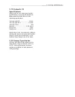
Page 27: ...ty 100 C 9 4 cSt Viscosity index 140 Density 0 89 g cm3 Pour point 40 C Flash point 227 C Depending on the circumstances different oils may be used in the telescopic handler Please consult the manufacturer of the handler if any changes are to be made 5 20 Grease Specification A heavy duty lithium type grease with a temperature range of at least 30 C to 140 C having good water and dust resistance s...

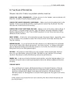
Page 28: ...may find that the belt needs to run a little faster for round bales If you cannot obtain this speed using valve 1 then return valve 1 to midway and adjust valve 2 Release locking nut and screw valve 2 in of a turn then lock the nut again Bring machine up to working speed again NO REV The pressure relief valves are very sensitive When starting the machine leave it 5 seconds before using any throttl...

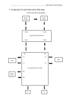
Page 29: ...rcuit Schematic 7 Hydraulic Circuit Schematic Drawing Flows shown when spreading Rotor Motor Rotor Motor M1B M2B Head Hydraulic Manifold M1A M2A M1 M2 C4 C3 C1 C2 Main Hydraulic Manifold M3 M4 Ram Ram Bed Motor V1 V2 ...

Reviews: