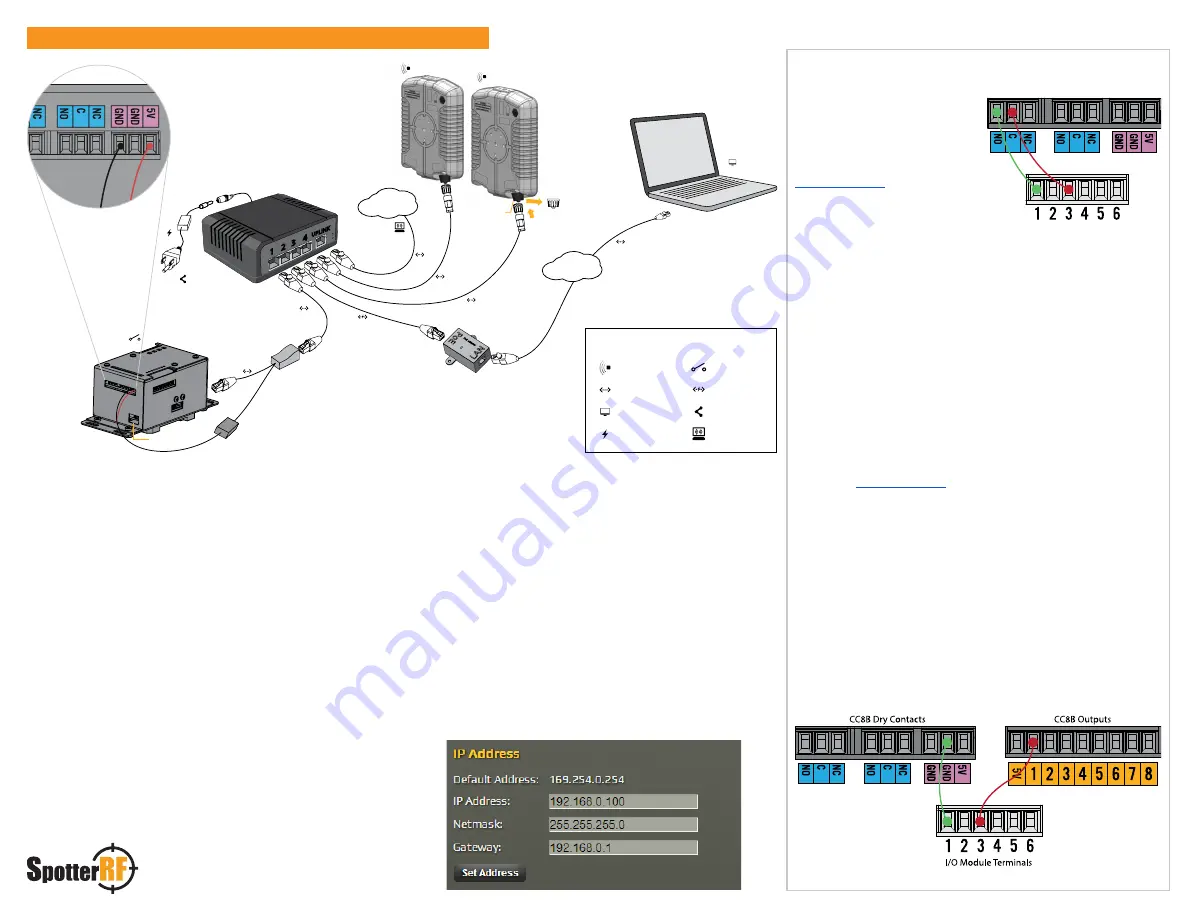
Step 1:
Connect CC8B to Power and Network
a. Connect the red wire from the PoE splitter to 5V DC port on the
CC8B.
b. Connect the black wire from the PoE splitter to the GND Terminal
on the CC8B.
c. Connect the Ethernet lead of the PoE splitter to the Ethernet port
of the CC8B.
d. Connect a network cable from the PoE splitter to a 12-30V DC PoE
power injector or switch.
Note:
5 V DC can be applied directly to the CC8B from an alternative 5V DC
supply rated 1 amp or greater either through the power terminals described
above or through the Micro USB Port.
Warning: Exceeding 5V DC could damage
the CC8B
Step 2:
Configure IP Settings
a. Connect a PC to the PoE Switch using the PoE Injector to strip
power as seen in diagram above.
b. Open Chrome on the connected computer and type
169.254.0.254 in the address bar; the landing page will load.
Note:
If your computer is set to a static IP address, you will not be able to
access the page without setting your IPV4 settings to obtain an IP address
automatically. To change this in Windows 7, open
Network and Sharing
Center
>
Change Adapter Settings
>
Local Area Connection
> select
Internet Protocol Version 4
, and change the settings to
Obtain an IP
address automatically
.
c. Click on the
GEAR
at the top right of the page then click
SETTINGS
, change the IP address, netmask and gateway to agree
with your network then click
Set Address
.
Example:
If your Network Gateway is 192.168.0.1 you might use the following
IP settings for the CC8B:
Optional step:
Connect Dry Contacts
Dry Contacts can be used to trigger
a number of external devices.
This example shows how to wire
dry contacts on the CC8B to
trigger events on an Axis Q7401
encoder. Page 61 of the Axis Q7401
shows how to
configure the I/O ports on the
encoder.
a. To connect dry contacts from
the CC8B to the encoder you
will need two wires (12–30
A.W.G.).
b. Connect one wire to the NO terminal of the CC8B and the other
end to terminal 1 (ground) of the encoder.
c. Connect the second wire to the adjacent C terminal of the CC8B
and the other end to terminal 3 (input 1) of the same encoder.
Note:
To test this connection, open the NetworekdIO interface, click the gear,
then click Actions. Under Available Actions, click on pins: Contact/DigitalOut 1
then click Test Action.
Optional Step:
Setup a Digital Output Trigger
Digital Output triggers can also be used to trigger a number of
external devices. This example shows how to wire digital outputs on
the CC8B to trigger events on an Axis Q7401 encoder. Page 61 of the
Axis Q7401
shows how to configure the I/O ports on
the encoder.
a. To connect digital output trigger 1 to the encoder you will need
two wires (12–20 A.W.G.).
b.
Connect the first wire to the GND terminal on the CC8B.
c. Connect the other end of the same wire to terminal 1 (ground) of
the encoder.
d. Connect the second wire to digital output terminal 1 of the CC8B.
e. Connect the other end of the same wire to terminal 3 (input 1) of
the same encoder.
Note:
To test this connection, open the NetworkedIO interface, click the gear,
then click Actions. Under Available Actions, click on pins: Contact/DigitalOut
1 then click Test Action. When you trigger either digital input 1 or 2, the
corresponding dry contact will also trigger.
Contact 1
Contact 2
CC8B Dry Contacts
Axis Encoder I/O Module Terminals
Power
Power
Contact 1
Contact 2
Ethernet port
Dust Cap
1 2
3 4
UPLINK
1 2
3 4
UPLINK
24V DC
Internet
Tycon model
TP-SSW5-NC
PoE splitter
Micro USB port
TCP/IP
Quickstart Guide - CC8B
Components
Radar
Ethernet cables
Computer
Power
CC8B
PoE Adapter
PoE Switch
Internet


