background image


T621 Repair Manual (Electronics)


Summary of Contents for T621

Page 1: ...T621 Repair Manual Electronics ...

Page 2: ...621 3 2 1 Troubleshooting Unit Will Not Start Operating T621 3 3 1 Troubleshooting Key Malfunction Display T621 3 3 2 Troubleshooting Key Malfunction T621 3 4 1 Troubleshooting Telemetry Heart Rate Malfunction T621 3 5 1 Troubleshooting Contact HTR Heart Rate Malfunction T621 3 6 1 Troubleshooting The Fuse Breaks at Start T621 3 6 2 Troubleshooting The Fuse Breaks at Motor Start T621 3 6 3 Trouble...

Page 3: ...nd Testing Motor Carbon brush T621 4 3 1 Inspecting and Testing wheel speed sensor T621 4 4 1 Inspecting and Testing Motor voltage T621 4 5 1 Inspecting and Testing Motor Thermal Sensor Test T621 4 6 1 Inspecting and Testing Incline Zero Switch Test T621 4 7 1 Inspecting and Testing Incline Motor Voltage Test T621 ...

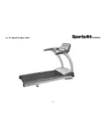
Page 4: ...1 1 Product Picture T621 1 1 1 ...

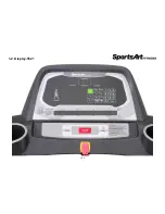
Page 5: ...1 2 Display T621 1 2 1 ...

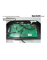
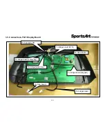
Page 6: ...1 3 Component Placement T621 Display 1 3 1 Telemetry heart rate receiver board Display board ...

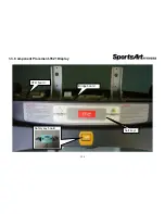
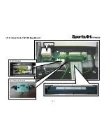
Page 7: ...1 3 Component Placement T621 Display 1 3 2 HTR board Bridge board Soft keys Safety key board ...

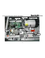
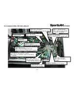
Page 8: ...1 3 Component Placement T621 Drive Board Area 1 3 3 Drive board AC incline motor Filter DC motor Speed sensor Temperature sensor Transformer ...

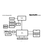
Page 9: ...iagram T621 1 4 1 Display board Drive board Motor Speed sensor Temperature sensor Incline motor Zero switch Transformer Filter HTR board Safety key Polar board Keypad SW FUSE AC1 AC2 Bridge board Sensor L Sensor R ...

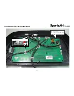
Page 10: ...1 5 Connections T621 Display Board 1 5 1 To drive board To bridge board keypad To bridge board safety key To bridge board fan To bridge board HTR To drive board To bridge board To telemetry HR ...

Page 11: ...1 5 Connections T621 Bridge Board 1 5 2 To safety key board To HTR board To display ...

Page 12: ...1 5 Connections T621 Drive Board 1 5 3 To incline motor To filter To motor To speed sensor To incline zero switch To display To motor temperature sensor ...

Page 13: ...1 6 Indicator LEDs T621 Display Board 1 6 1 HR indicator Power indicator Lit indicates display has power ...

Page 14: ...ctive function is activated LED3 CUS_DN Indicator Lit Cushion motor is retracted soft LED2 POWER Indicator Lit Power is supplied LED10 Motor Thermal Switch Indicator Lit Motor is overheated protective function is activated LED1 SOFT Indicator Lights automatically two seconds after powering up LED5 EMG Indicator Lit There is voltage to the motor Not lit Emergency stop switch is activated LED9 UP In...

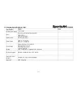
Page 15: ...ion Speed sensor Infrared optic sensor Speed Range KPH 0 2 20 0 KPH MPH 0 1 12 0 MPH Incline Range Power AC motor 110V or 220V Incline range 0 15 0 setting time control 1 per 2 seconds Display LED 16 segment 7 segment LED dot matrix Workout Programs MANUAL RANDOM HILL INTV GLUTE Heart rate control program CARDIO WT LOSS ZONE TRAINER Heart rate HTR Telemetry 1 7 1 ...

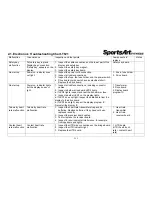
Page 16: ...cables 2 Inspect whether drive board LED2 lights a If LED2 lights inspect and test the transformer fuse 3 Inspect whether LED1 on the display lights a If LED1 does not light inspect the data cable from the display to the drive board b If LED1 does light inspect the display program IC Re install the display IC 1 Transformer 2 Drive board 3 Display board program IC Telemetry heart rate malfunction T...

Page 17: ... replace the drive board 4 Inspect the motor brushes and the commutator 1 Drive board 2 Motor brushes commutator ERR 1 Motor rotate ERR1 appears 1 The program did not detect the optic sensor signal 2 Inspect the CLK indicator on the drive board If the CLK indicator is not lit clean or replace the speed sensor If the CLK indicator lights normally inspect the data cable from the display to the drive...

Page 18: ...y shows SERVICE REQUIRED TREADMILL SHUTTING DOWN STOPPING 1 Motor thermal protection unit is activated Let the unit rest half an hour or more to cool 2 If this message often appears please inspect the treadmill walk belt and deck Lubricate if necessary 3 If the walk belt is worn replace the walk belt SERVICE NEEDED APPLY LUBE SERVICE NEEDED APPLY LUBE 1 This lubrication prompt appears every 4000 K...

Page 19: ...ety key board malfunction Troubleshooting 1 Inspect the safety key magnet 2 Inspect the bridge board cable connections 3 Test or replace the safety key board 3 1 1 Display board Bridge board Safety key board Bridge board Safety key connection Safety key safety key board Safety key reed switch test With safety key Reed switch ON Without safety key Reed switch OFF Reed switch ...

Page 20: ...upply or component malfunction Troubleshooting 1 Inspect the power cable connection 2 Inspect cable connections under the motor cover 3 Inspect the main fuse fuse holder and the power switch 4 Inspect drive board components for signs of burning Or replace the drive board as a test 3 2 1 Drive board Display board Filter SW FUSE AC1 AC2 Drive board Fuse fuse holder switch ...

Page 21: ...ormer fuse and measure transformer input and output voltage 3 Inspect whether LED1 on the display board lights A If it does not light inspect cable connections from the display to the drive board B If it does light inspect the display IC Re install the display IC 3 2 2 Drive board Display board Transformer FUSE AC1 AC2 LED LED Filter Power led Transformer voltage Transformer voltage AC red red blu...

Page 22: ...ress display keys The display shows no reaction Or keys operate continually Possible cause 1 Wires to the display board are not connected properly 2 Soft keys are bad Troubleshooting 1 Inspect soft key connections 2 Replace the soft keys 3 3 1 Display board Keypad Soft key connection Soft key ...

Page 23: ...splay shows no reaction or keys operate continually Possible cause 1 Soft key malfunction 2 The bridge board soft key connections are not connected properly Troubleshooting 1 Inspect soft key wire connections 2 Replace the soft keys 3 3 2 Soft key Display board Bridge board Bridge board Soft key connector ...

Page 24: ...ironmental noise such as lights or speakers interferes with reception Troubleshooting 1 Replace transmitter or its batteries 2 Inspect the telemetry heart rate receiver 3 Replace the telemetry heart rate receiver 3 4 1 Heart rate receiver board Display board Transmitter Heart rate transmitter battery location Telemetry heart rate receiver board Red LED is heart rate signal indicator Heart rate boa...

Page 25: ...ge board HTR cable connections 3 Inspect contact heart rate cable connections 4 Inspect the HTR board indicator LEDs 5 Replace the HTR board 3 5 1 Bridge board Display board HTR board Sensor L Sensor R HTR Indicators LED Name Function LED1 POLAR LED Flashing indicates incoming telemetry signal LED2 HTR contact LED Lit indicates user is gripping HTR contact LED3 HTR signal LED Flashing indicates in...

Page 26: ...ave an abnormal electrical short 2 Drive board component malfunction Troubleshooting 1 Inspect the power cord Is the cord insulation broken and creating an electrical short 2 Replace the drive board as a test Drive board malfunctions are the most common source of blown fuses 3 Replace the EMI filter 3 6 1 Drive board Filter SW FUSE AC1 AC2 Drive board ...

Page 27: ...otor rotates Then the fuse blows Possible cause 1 Motor windings have an electrical short 2 Drive board malfunction Troubleshooting 1 Replace the drive board as a test 2 Replace the motor as a test 3 Replace the speed sensor as a test 3 6 2 Drive board Display board Sensor Motor Drive board Motor Sensor ...

Page 28: ...function 2 Deck or belt wear 3 Drive board malfunction Troubleshooting 1 Inspect the fuse and fuse holder installation 2 Inspect the mechanics A Is the walk belt worn or requiring lubrication B Inspect walk belt tightness Is it too loose 3 Replace the drive board as a test 4 Inspect the motor brushes 3 6 3 Drive board Display board Sensor Motor motor ...

Page 29: ...ons 2 Inspect the display board IC connection 3 Measure motor voltage from the drive board Is there voltage across M M If not replace the drive board If so A inspect transformer output voltage B inspect whether the EMG LED lights C inspect whether IGBTs have an electrical short 4 Inspect motor brushes and the commutator 3 7 1 Drive board Display board Motor Transformer Sensor motor Inspect motor b...

Page 30: ...oting 1 Inspect all cable connections 2 Inspect whether the LED6 indicator on drive board flashes If not the optic sensor is malfunctioning Either clean the optic sensor sensor head or replace the optic sensor 3 If the LED6 indicator lights inspect the cable connections and main IC connections 3 7 2 Drive board Display board Sensor Motor motor LED6 MC indicator Optic sensor ...

Page 31: ...e 1 Optic wheel teeth or optic sensor malfunction 2 Drive board malfunction Troubleshooting 1 Inspect whether optic wheel teeth are missing 2 Replace the optic sensor as a test 3 Replace the drive board 3 8 1 Drive board Display board Sensor Motor LED6 MC Inspect the optic sensor and optic sensor wheel teeth ...

Page 32: ...g 1 Inspect whether incline UP or DN LEDs light during operation 2 Drive board voltage follows Drive board Incline motor voltage LED9 UP lit White Black 110V or 220V LED7 DOWN lit White Black 110V or 220V 3 When the incline is at the 0 position does it touch the zero switch Does LED8 light 3 9 1 Drive board Display board Incline motor Zero switch Incline up down LED LED8 zero switch Incline connec...

Page 33: ... is overheating Please turn off the unit and allow it to rest for one hour 2 Inspect whether the motor thermal sensor is normal 3 If the message appears often the walk belt might require lubrication or be worn out Lubricate or replace the walk belt as needed 4 If these measures aren t effective replace the walk deck or motor 3 10 1 Drive board Display board Temp sensor Motor Temperature sensor Tem...

Page 34: ... display shows TIME XXXXXX HOUR Press the ENTER key to proceed to view more information 5 Software version numbers for display board and drive boards appear one after another After each bit of information appears press the ENTER key to proceed After the drive board software version appears pressing the ENTER key brings you to the startup banner screen Model T621 Item Clear total distance and time ...

Page 35: ...vate the lubrication mode The display counts down 3 2 1 The speed window shows 2 0 KPH or 1 3 MPH and the walk belt starts rotating 3 Squeeze the bottle of lubricant into the applicator tube Let the unit operate slowly for ten minutes Allow the lubricant to disperse onto the walk belt 4 After ten minutes press the STOP key and remove the lube applicator tube The display program will clear the lube...

Page 36: ...tructions Model T621 Item Error messages E 1 Display board main program has not received the optic sensor signal E 3 Display setting and actual speed differ E 7 Incline motor calibration point abnormality 3 13 1 ...

Page 37: ...ure transformer voltage 3 Set the multi meter to the AC setting Place probes as follows 4 1 1 Transformer connector Transformer fuse Transformer cables Voltage red red or blue blue input voltage 110V red 220V blue black black normal power 12 5V white white normal voltage 12 5V orange orange incline voltage 29V yellow yellow normal voltage 11 5V ...

Page 38: ...d be smooth If there are grooves the commutator might be faulty C Inspect whether brush copper wires have changed color If so replace the brushes 4 2 1 Brush ends shown here have scratches a sign of irregular wear Replace brushes like these Brush length should exceed 0 7 mm This image shows brushes that are too short If copper wires have changed color connections are bad Replace the brushes Motor ...

Page 39: ...tic wheel to move Inspect whether LED7 on the drive board flashes When a tooth of the optic wheel is in the center of the optic sensor LED7 on the drive board does not light When a tooth of the optic wheel is not in the center of the optic sensor LED7 on the drive board lights 4 The optic sensor includes an infrared transmitter and a receiver Inspect whether the optic sensor is dirty If so wipe it...

Page 40: ...t the VDC setting on the multi meter Place probes on M M connectors on the drive board 2 Press the SPEED key The motor should operate allowing you to measure motor voltage Speed Drive board voltage Motor specifications Highest speed 100 120 VDC 110V Lowest speed 210 230 VDC 220V 4 4 1 Place probes on M M connectors ...

Page 41: ...sor wire Drive board LED10 will light The display will show SERVICE REQUIRED Connect the temperature sensor wire LED10 on the drive board will not light 3 When the motor is too hot LED10 will light and the treadmill will stop operating Please stop the unit and wait one hour before use If the same issue occurs again lubricate the walk belt and deck 4 5 1 Temperature sensor indicator LED Temperature...

Page 42: ...At 1 15 the zero switch is not touched by the worm gear The zero switch is off LED8 does not light 4 6 1 Led8 zero switch Zero switch Incline 0 1 15 Tube Touches switch Does not touch switch Zero switch on off Picture Drive board Led 8 light Led 8 no light Led 8 indicator Zero switch Zero switch Incline 0 1 15 Worm gear Touches zero switch Does not touch zero switch Picture Zero 開關 on off ...

Page 43: ...ure voltage output to the incline motor Normal readings are shown below Display Drive board Incline motor cables Incline operates Press key Led9 UP lights white black 110V or 220V upward Press key Led7 DOWN lights white red 110V or 220V downward 4 7 1 Display Drive board LED9 UP LED7 down Incline motor Red Black White Incline motor connector LED9 incline up Indicator LED7 incline down Indicator In...

Reviews: