Customer Service 1-888-707-1880
Dyaco Canada Inc. 2021
Email: [email protected]
14
STEP 2
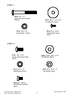
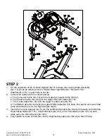
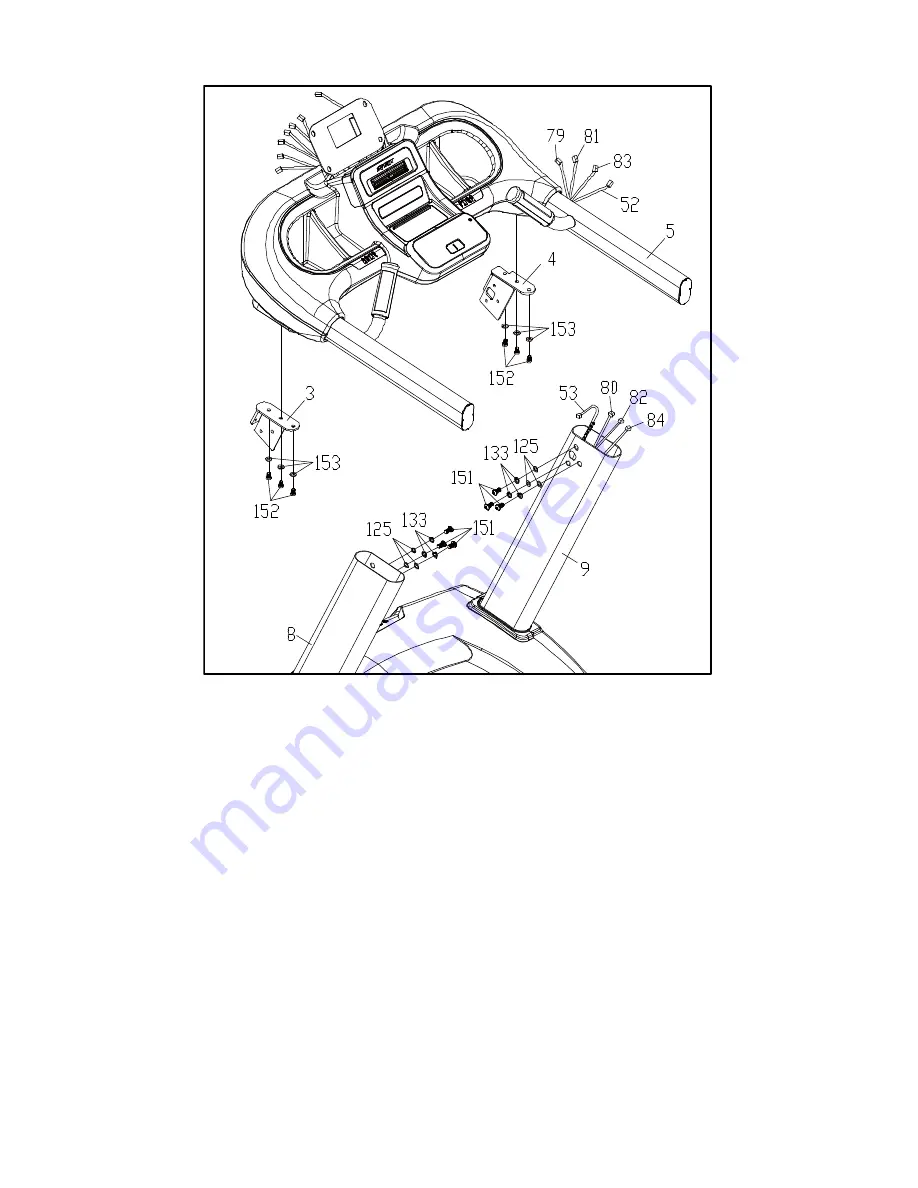
1. On the underside of the Console Support (No.5) is where the Locking Plate Assembly
(No. 3 & 4) can be attached. Use 3 Socket Head Cap Bolts (No.152) and 3 Flat
Washers (No.153) on each side to secure.
2. Connect all cables with the correct pairing:
a. The Computer Cable (No. 53) with the Upper Computer Cable (No.52).
b. The Ethernet Cable (No. 80) with the Upper Ethernet Cable (No.79).
c. The C-safe Cable (No. 82) with the Upper C-safe Cable (No.81).
d. The HDMI Cable (No. 84) with the Upper HDMI Cable (No.83). Note: Be careful not to pinch the
wires and slide them into the Right Upright (No.9).
3. Insert the Console Support (No.5) into the Left/Right Uprights (No.8 & 9) and secure with 3 Button
Head Socket Bolts (No.151), 3 Split Washers (No.133), and 3 Flat Washers (No.125) on both
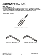
sides using the Allen Wrench (No.160).
4. Fully tighten five sets of bolts (No.150) to Right/Left Uprights (No.9/No.8) to Main Frame.


