background image

SPT-N11U and SPT-N12U Chassis Installation Instructions

Certifications and Standards

4

|

SPT-N11U and SPT-N12U Installation Instructions

P/N 71-008728  Rev A, August 2019

noted, forward an immediate request to the delivering carrier to perform an inspection and 
prepare a damage report. Save the container and packing material until contents are 
verified or in case the equipment will be transported at a later date.

Report the nature and extent of damage to Spirent Communications Customer Support so 
that action can be initiated to repair or replace damaged items or instructions can be 
provided for returning items.

The responsibility of the manufacturer ends with delivery to the first carrier. All claims for 
loss, damage, or nondelivery must be made against the delivering carrier within 
10 calendar days of receipt of shipment.

Important:  

The SPT-N11U/SPT-N12U weighs over 100 lbs and will require at least four 

people to move and install it. The preferred method is to install it using an IT equipment 
lift designed for heavy network equipment.

Open the packaging carefully and save all packaging materials. Safely shipping the SPT-
N11U/SPT-N12U requires the use of the included pallet, custom-fit foam, and shipping 
box. Set these materials aside for future use. Set aside the accessories and power supplies. 
These will be needed later. Carefully lift the chassis out of the box using the side and front 
handles and securely place it on a level and stable surface.

Damaged or Missing Equipment

If any equipment is damaged or missing, call (800) 774-7368 or (818) 676-2616 
(international) for technical support. Registered users may also access the Spirent 
Communications support website a

https://support.spirent.com

You may also email 

questions to

[email protected]

.

Certifications and Standards

FCC

The SPT-N11U/SPT-N12U chassis complies with the limits for a Class A digital device in 
accordance with Part 15 of the FCC Rules. These limits are designed to provide 
reasonable protection against harmful interference when this equipment is operated in a 
commercial environment. Operation is subject to the following two conditions:

This device may not cause harmful interference.

This device must accept any interference received, including interference that may 
cause undesired operation.

This device generates, uses, and can radiate radio frequency energy if not installed and 
used in accordance with the instructions in this manual. Operating this equipment in a 
residential area is likely to cause harmful interference, and the customer will be required 
to rectify the interference at his or her own expense. This product requires the use of 
external shielded cables to maintain compliance pursuant to Part 15 of the FCC Rules.

Summary of Contents for SPT-N11U

Page 1: ...document is intended to guide you to a safe and successful installation of the Spirent SPT N11U or SPT N12U mainframe chassis In this document Certifications and Standards 4 Introduction 7 Site Selec...

Page 2: ...cordance with the Software License Agreement the Software which it supplies will operate in material conformity with the specifications supplied by Spirent for such Software for a period of ninety 90...

Page 3: ...7 dB A weighted sound power level LWA as measured per ISO 3741 Sound Power Noise Measurement and appropriate ear protection should be worn when working in proximity to the chassis Please contact your...

Page 4: ...se Set aside the accessories and power supplies These will be needed later Carefully lift the chassis out of the box using the side and front handles and securely place it on a level and stable surfac...

Page 5: ...nterference Characteristics of Information Technology Equipment EN 55024 Limits and methods of measurement of immunity characteristics for information technology equipment EN 60950 Safety of Informati...

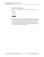
Page 6: ...ins material that presents an environmental concern Spirent encourages users of Spirent provided electrical and electronic equipment to not dispose of the labeled products in waste collection units wh...

Page 7: ...nd both ventilation locations must remain unobstructed for proper operation Inadequate cooling or airflow can result in an over temperature situation that will cause an automatic system shut down The...

Page 8: ...45 cm x 48 9 cm x 84 6 cm 30 76 2 cm depth measured from front mounting flange Installation and shipping weight 125 lb 58 6 kg 3 system and 2 slot PSUs and fans installed no test modules installed App...

Page 9: ...SPT N11U Built in LCD display SPT N12U Front panel LEDs Temperature fan admin link system and system power status Test module slot power status Rear panel LEDs Admin Ethernet link speed and activity C...

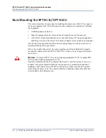
Page 10: ...h chassis for four post rack mounting The chassis is shipped standard with a front mounting flange for four post racks and a mid mount flange for two post racks Due to the weight of the system the pow...

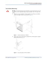
Page 11: ...ng the front rack ears There is a risk of equipment damage and personal injury due to the weight of the system 1 Attach the center mount brackets with the supplied screws if they are not already secur...

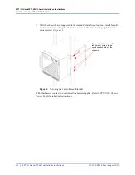
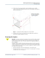
Page 12: ...in the intended installation location install four 4 rack mount screws through each rack ear and into the rack totaling eight 8 rack mount screws Figure 3 Figure 3 Securing the Center Mount Brackets...

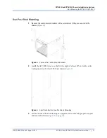
Page 13: ...with a screwdriver if they are secured to the chassis Figure 4 Figure 4 Remove the Center Mount Brackets 2 Install the ACC 2021A tray or a shelf with a depth of at least 30 and with a static loading...

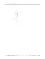
Page 14: ...SPT N12U Chassis Installation Instructions Rack Mounting the SPT N11U SPT N12U 14 SPT N11U and SPT N12U Installation Instructions P N 71 008728 Rev A August 2019 Figure 6 Using an Equipment Lift for...

Page 15: ...connected to a 15A circuit with no other connected equipment and each with its own breaker Installation of this chassis must comply with local and national electrical codes If necessary consult with...

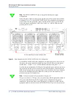
Page 16: ...fans moving to the left the next socket powers module slots 1 4 then 5 8 etc with the leftmost socket powering slots 9 12 For either chassis configuration if all the slots for a particular power socke...

Page 17: ...chassis Using the ACC 2018 Hypermetrics Dual slot Card Carrier Describes the procedure for installing and removing test modules that require card carriers for use in the SPT N11U SPT N12U and SPT N4U...

Page 18: ...Pacific Time Europe Middle East Africa E mail support spirent com Web https support spirent com Phone 33 1 6137 2270 France Phone 44 1803 546333 UK Hours Monday through Thursday 09 00 to 18 00 Friday...

Reviews: