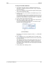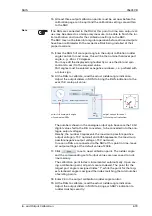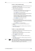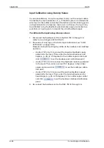
056357/B
RAIS
7-2
General Troubleshooting Instructions
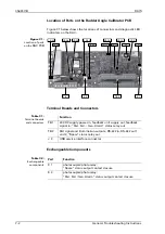
Location of Parts on the Rudder Angle Calibrator PCB
Figure 7-1 below shows the locations of connectors and diagnostic LED
indicators on the RAC.
Figure 7-1:
Location of parts
on the
RAC PCB
Terminal Boards and Connectors
Table 7-1:
Terminal boards
and connectors
Exchangeable Components
Table 7-2:
Exchangeable
components
TB 1
TB 2
CR 34
CR 20
CR 17
J 3
CR 4
CR 33
CR 29
CR 23
CR 16
CR 13
CR 12
CR 9
CR 28
K 2
K 1
Function
TB 1
24 VDC supply power in, feedback unit supply out, feedback
signal in, “Pwr. Fail. / Gen. Alarm” status relay out
TB 2
RAI signal and illumination outputs, RS-422 in, RS-422 out 1
and 2, “Spare” status relay out
J 3
USB service interface connector
Part
Function
K 1
photocoupler/photo relay;
“Spare” status output contact closure
K 2
photocoupler/photo relay;
“Pwr. Fail / Gen. Alarm” status output contact closure
Summary of Contents for Rudder Angle Indicator System
Page 18: ...056357 B RAIS 1 10 Declaration of Conformity...
Page 20: ...056357 B RAIS 2 2 Normal Operational Mode...
Page 26: ...056357 B RAIS 3 6 Viewing RAC Errors through SUSI...
Page 28: ...056357 B RAIS 4 2 Maintenance by Service Personnel...
Page 58: ...056357 B RAIS 7 4 General Troubleshooting Instructions...
Page 64: ...056357 B RAIS 8 6 Replacing Alarm Output Relays...
Page 95: ......
Page 96: ......
Page 97: ......
Page 98: ......
Page 99: ......
Page 100: ......
Page 101: ......
Page 102: ......
Page 103: ......
Page 104: ......
Page 105: ......
Page 106: ......
Page 107: ......
Page 108: ......
Page 109: ......
Page 110: ......
Page 111: ......
Page 112: ......
Page 113: ......
Page 114: ......
Page 115: ......

