

To Change Channel 5 to X-port or X-port to Channel 5
Note:
When X-Port is active, CH5 and CH6 are not available; however, reversed aileron (CH2) is still
available.
Note:
All changes made in advanced programming must start with the receiver powered down to prevent
the motor from running unexpectedly.
To safely accomplish advanced programming feature changes, please enlist the use of a helper. One to
hold the aircraft to prevent unintended flyaways, and one to make the changes on the transmitter.
Sticks must be held in this position while the transmitter is on and the receiver is off.
1. Ensure a successful bind was completed
2. Plug the X-Port accessory or the optional servo into the X-Port/CH5
3. Turn the transmitter on
4. Move the THRO stick to the full throttle position
5. Move Control sticks to the corresponding position to change between the available options. (see
illustration)
6. While holding this position, plug the battery into the receiver, power receiver
7. The LED on the receiver will go solid and within 5 seconds the LED will flash 3 times quickly,
indicating the option is now changed
8. Disconnect battery from receiver
9. Turn transmitter off
Optional Support Items
PKZ3502
Propeller with Spinner: Sukhoi (160mm x 70mm)
PKZ3516
Motor: Sukhoi (8.5mm diameter, 20mm length)
PKZ3527
Gearbox without Motor: Sukhoi (Gear ratio 4:1)
PKZ3528
Propeller Shaft: Sukhoi
PKZ3302
Propeller with Spinner: Vapor (140mm x 45mm)
PKZ3316
Main Motor: Vapor (6.0mm diameter, 15mm length)
PKZ3327
Gearbox without Motor: Vapor (Gear ratio 6:1)
PKZ3328
Propeller Shaft with Gear (2): Vapor
PKZ1034
110mAh 1S 3.7V LiPo: Sukhoi
PKZ3001
3.7V 70mAh LiPo Battery: Cessna 210, Citabria, Ember/2, Vapor
EFLB1101S
110mAh 1S 3.7V LiPo: Blade mCX
EFLC1003
1S 3.7V LiPO Charger, 0.3A: Blade mCX
EFLC1004
E-flite Celectra 4 Port Charger for 1C 3.7V LiPo battery packs
PKZ3240
DC 3.7V LiPo Charger
Receiver Installation
It is recommended to use double-sided foam tape strips and/or minimal hot glue in the corners to
install your receiver in the fuselage. Note that the servos need to be in the appropriate position to attach
to and drive the elevator and rudder pushrods. Note: Installation will vary depending upon application.
Servos
The AR6400 incorporates integrated servos; optional servos are also available through Spektrum
(SPMAS2000). Note that using any other servo may cause damage to the receiver and/or the servo and
may void the warranty.
Installing and Plugging in the Optional Servos
Use double-sided foam tape strips and/or minimal hot glue to mount the servos in place. Note that the
servos need to be in the appropriate position to attach to the corresponding pushrods. Plug the servo
leads into the appropriate servo ports in the receiver noting the polarity of the servo connector. Note:
Installation will vary depending upon application.
AR6400 User Guide
The AR6400 6-channel Ultra-Micro
™
receiver with integrated servos, speed control and X-Port
™
technology is designed for ultra-micro aircraft. Featuring DSM2
™
technology the AR6400 is compatible
with all Spektrum
™
, JR
®
, E-flite
®
and ParkZone
®
2.4GHz DSM2 technology transmitters including:
Spektrum DX7, DX6i, DX5e, Spektrum Module Systems, JR12X, JRX9303, E-flite LP5DSM, E-flite
HP6DSM, E-flite MLP4DSM and ParkZone’s 2.4GHz DSM2 Transmitter.
US Patent D578,146. Other Patents Pending.
Note:
The AR6400 receiver is not compatible with the DX6 park flyer radio system.
Features
• 6-channel Ultra-Micro receiver
• Two integrated linear servos (elevator and rudder)
• Integrated brushed speed control
• Compatible with external brushless speed controls (optional)
• Weighs just 3.9 grams
• Compatible with optional Spektrum 1.5-gram linear ultra-micro servos SPMAS2000
• Smart Bind™ technology
• X-Port allows for future expansion
Applications
The AR6400 is designed for ultra-micro aircraft and is ideal for scratch-built ultra-micro
projects. The AR6400 is designed to utilize a single cell LiPo battery. Two sizes are
available, EFLB1101S 3.7V 110mAh, PKZ3001 3.7V 70mAh and PKZ1034 3.7V 110mAh.
An integrated brushed speed controller can be used to power a brushed motor up to 2
amps of continuous current or an optional brushless controller can be used. An integrated
X-Port feature allows for future expansion.
Note:
when X-Port is active, CH5 and CH6 are not available; however, reversed aileron
(CH2) is still available.
Specifications:
Type: DSM2 micro receiver with integrated brushed speed controller and two linear
servos
Channels: 6 channels or 4 channels plus X-Port
Modulation: DSM2
Dimension (WxLxH): 27.75 x 23.45 x 8.10mm
Weight: 3.9 g
Input Voltage Range: 1-cell LiPo 3.2 to 4.2V
Antenna Length: 31mm
Resolution: 1024
Compatibility: All DSM2 aircraft transmitters
Servos:
Force: 2.8 oz
Stroke: 7.4mm
Speed: 0.14 sec
Speed Controller:
Type: Integrated brushed
Max continuous current: 2.0 amps
Smart Bind
™
The AR6400 receiver must be bound to the transmitter before it will operate. Binding is the process of
teaching the receiver the specific code of the transmitter so it will only connect to that specific transmitter.
The AR6400 features Smart Bind. When the receiver is first powered, the receiver will look for the signal of
its previously bound transmitter for 5 seconds. If no signal is found the receiver will automatically go into
bind mode indicated by the flashing LED.
Binding
1. Make sure the flight battery is fully charged.
2. Confirm the flight battery is disconnected from the receiver/ESC unit and the transmitter is turned off.
3. Plug the flight battery into the receiver’s battery connector. After 5 seconds the LED on the receiver unit
will begin flashing indicating it is in bind mode.
4. After verifying the LED is flashing on the receiver, follow the steps necessary that allow your transmitter to
enter bind mode. (See your transmitter’s manual or the supplement on the following pages.)
5. If you entered bind mode correctly, you will see a solid LED within about 10 seconds. You should now be
bound to the transmitter and have full control and function.
IMPORTANT: After Binding
Once the system is bound, the transmitter should always be turned on first and then the receiver to prevent
the receiver from re-entering bind mode. If your receiver inadvertently enters bind mode, simply unplug
the battery from the receiver and reinstall with the transmitter remaining on.
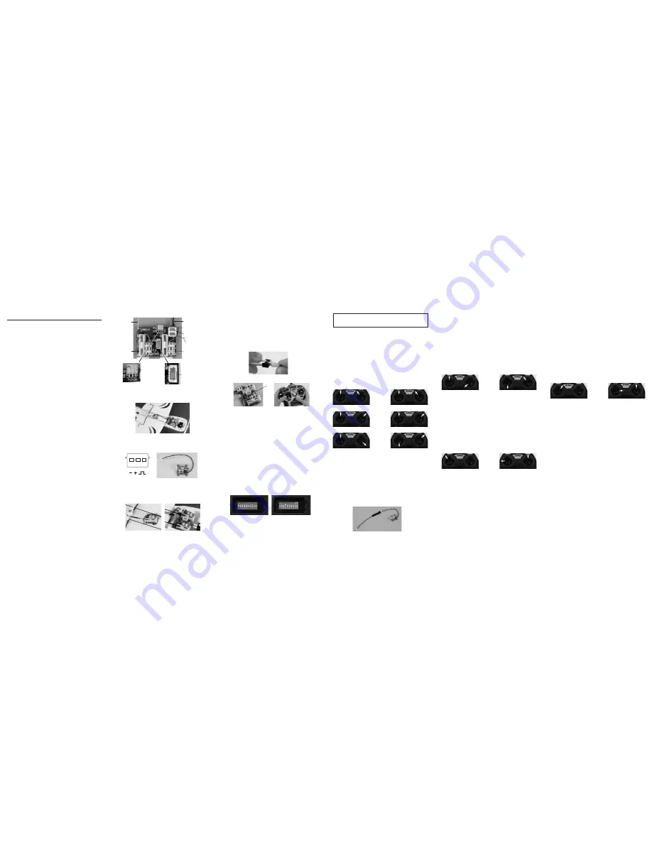
Advanced Programming Features
The following programming features are only recommended for advanced radio users. To safely accomplish
advanced programming feature changes, please enlist the use of a helper. One to hold the aircraft to prevent
unintended flyaways, and one to make the changes on the transmitter. The photos in this section show the E-flite
MLP4DSM transmitter, however, the procedures apply to all compatible transmitters.
Prior to making any advanced programming feature changes it is necessary to:
Computer Radios like the DX6i, DX7
1. Choose an empty model location
2. Select model type ACRO
3. Perform a model reset
4. Set all channels to normal reversing
5. Ensure a successful bind has been established
Note:
Please secure the aircraft safely to a work bench or enlist the use of a helper while accessing the advanced
programming features. Mistakes in programming could cause the motor to run unexpectedly.
LP5DSM, HP6DSM
If you decide to use an E-flite LP5DSM or HP6DSM transmitter, please position your channel reversal dip
switches as follows:
Note:
Keep a record of the existing settings in case you want to go back and fly your other aircraft.
Reversing Servos
Servo reversing may be achieved using the servo reversing function of your transmitter, or as
certain advanced applications require it, you may reverse the actual servos by following the
instructions and diagrams below.
Reversing The Servos on the Receiver Board
This feature reverses the servos at the board level, making it useful for implementing features such as
elevons while using transmitters with limited programming options.
Note:
All changes made in advanced programming must start with the receiver powered down to prevent
the motor from running unexpectedly.
To safely accomplish advanced programming feature changes, please enlist the use of a helper. One to
hold the aircraft to prevent unintended flyaways, and one to make the changes on the transmitter.
Sticks must be held in this position while the transmitter is on and the receiver is off.
1. Ensure a successful bind was completed
2. Turn transmitter on
3. Move THRO stick to full throttle position
4. Move control sticks to the corresponding position for the servo to be reversed (see illustration)
5. While holding this position, plug the battery into the receiver, power receiver
6. The LED on the receiver will go solid and within 5 seconds the LED will flash 3 times quickly,
indicating servo is now reversed
7. Disconnect battery from receiver
8. Turn transmitter off
Reversing Optional 1.5-Gram Servo
Reversing the servo is useful when implementing certain installations, such as dual ailerons, flaps, etc.
Spektrum offers a servo reversing lead that can be plugged between the receiver and the optional 1.5-gram
servo.
Note:
All changes made in advanced programming must start with the receiver powered down to prevent
the motor from running unexpectedly.
To safely accomplish advanced programming feature changes, please enlist the use of a helper. One to
hold the aircraft to prevent unintended flyaways, and one to make the changes on the transmitter.
To reverse servo using the reversing lead:
1. Plug the reversing lead into the servo
2. Plug servo into CH2 or Reversed CH2/CH6 ports
3. Power receiver using a charged battery
4. Once receiver connects, the servo is now reversed
5. Disconnect battery from receiver
6. Remove servo reversing lead (be sure to store your reversing lead in a safe place for future use)
7. Reinstall servo lead into servo port
To Change Channel 6 to a Reversed Channel 2 for Dual Ailerons
or Reversed Channel 2 to Channel 6
Note:
All changes made in advanced programming must start with the receiver powered down to prevent
the motor from running unexpectedly.
To safely accomplish advanced programming feature changes, please enlist the use of a helper. One to
hold the aircraft to prevent unintended flyaways, and one to make the changes on the transmitter.
Sticks must be held in this position while the transmitter is on and the receiver is off.
1. Ensure a successful bind was completed
2. Turn transmitter on
3. Move THRO stick to full throttle position
4. Move Control sticks to the corresponding position to change between the available options (see
illustration)
5. While holding this position, plug the battery into the receiver, power receiver
6. The LED on the receiver will go solid and within 5 seconds the LED will flash 3 times quickly,
indicating the option is now changed
7. Disconnect flight pack from receiver
8. Turn transmitter off
To Change the Brushed Motor to Operate an Optional Brushless Motor ESC or Brushless to
Brushed Motor Control
The AR6400 is capable of operating brushless motors with the use of an optional brushless ESC, please
see the illustration below for instructions.
Sticks must be held in this position while the transmitter is on and the receiver is off.
1. Ensure a successful bind was completed
2. Turn transmitter on
3. Move THRO stick to full throttle position (see illustration)
4. Move Control sticks to the corresponding position to change between the available options (see
illustration)
5. While holding this position, plug the battery into the receiver, power receiver
6. The LED on the receiver will go solid and within 5 seconds the LED will flash 3 times quickly,
indicating the option is now changed
7. Disconnect battery from receiver
8. Turn transmitter off
LED
Optional Servo (SPMAS2000)
AR6400 Features and Ports
THRO/RUDD ELEV/AILE
ELEV/RUDD THRO/AILE
CH4
1. Full THRO
2. Up ELEV
3. Right AILE
Mode 1
CH2
1. Full THRO
2. Down ELEV
3. Left AILE
THRO/RUDD ELEV/AILE
THRO/RUDD ELEV/AILE
ELEV/RUDD THRO/AILE
ELEV/RUDD THRO/AILE
CH3
1. Full THRO
2. Down ELEV
3. Right AILE
Mode 2
Mode 1
THRO/RUDD ELEV/AILE
ELEV/RUDD THRO/AILE
Rev. CH2/CH6
1. Full THRO
2. Up ELEV
3. Left AILE
Mode 2
Mode 1
THRO/RUDD ELEV/AILE
ELEV/RUDD THRO/AILE
1. Full THRO
2. Left RUDD
Mode 2
Brushed/
Brushless
Mode 1
THRO/RUDD ELEV/AILE
ELEV/RUDD THRO/AILE
1. Full THRO
2. Right RUDD
Mode 2
CH5/X-port
LP5DSM Transmitter
HP6DSM Transmitter
Antenna
Rudder (CH4)
servo
X-Port (all 4 pins)
OR
Gear (CH5) (lower 3 pins)
Aileron (CH2)
Battery input
Reversed Aileron (CH2)
or
Aux1 (CH6)
Elevator (CH3)
servo
Brushed Motor output
(– + open)
– + open
+ –
ESC Brushless
( – )