


Getting Started
Spectral Products
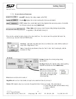
3.2. Setup Screen
The detector setup screen appears first. The following pages assumes the user has selected in this screen a
system using the AD111 detector with a CM or DK Digikrom Monochromator.
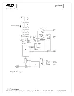
Figure 4
SPAD111.vi Setup Screen
•
COM port:
Set this value to an open
com port for the AD111 Detector.
•
time delay
sets the time in ms to wait
before echo back.
•
error code
:
Any value here other than
0 indicates a communication problem
with the AD111.
•
High Voltage
controls the voltage
supplied to the PMT between 0 – 1000
volts. Too small a value will not
produce a signal large enough for
amplification. Larger values produce
more signal but higher anode dark
current noise.
•
RC
sets the time constant for detector.
•
Gain
sets the electronic gain for the
system. Larger values
produce more
signal but higher noise.
•
Trigger Source:
Ext. Trigger allows AD111 to operate using an external triggering from the Trigger In port on the
controller
Level Trigger causes the AD111 to ignore external voltages below a certain value (as set by
Trigger
Level
)
SW Trigger: Internal triggering through the software
•
Actual HV:
Should read close to the set value of HV
•
Trigger Level
sets the value for Level Trigger. Selectable values between 0 – 50 correspond to 0 – 5
volts.
•
Sample Avg:
Number of readings to average into a single data point
•
Signal
sets the data collected. The switch toggles between signal out from
PMT
or High Voltage (
HV
)
supplied to PMT.
•
HV Ctrl Source
sets the source for the high voltage supplied to the PMT. The switch toggles between
External (
Ext.(0-10Vdc
) and Internal software specified (
Int. (USB)
).
•
System
selects the configuration of either using AD111 alone or with a CM or DK series Digikrom
Monochromator.
•
# of Pulses
(Ext. Trigger and Level Trigger only)
:
sets the number of triggered pulses to be averaged
into a single data point.
•
Memories to Save Samples/P(4-512)
(Ext. Trigger and Level Trigger only)
:
The system may collect
more than one sample for each triggered pulse.
The user must
set this to a value larger than or equal to
the number of samples that will be acquired. Setting this number close to the actual number of samples
will save on RAM. Start with the following: [Time between pulses in
μ
s]
÷
29.
Spectral
Products
2659 Pan American Fwy, Suite A, NE Albuquerque, NM 87107 Ph. (505) 343-9700 Fax (505) 343-9705
9


