


11.
Attach hinge halves to the unit with the hinge facing towards the front.
12.
Pinch the hinge pins together into the stored position. Align the hinge halves together
between the two units, and swing together side by side. The hinge pins should snap into
place, securing the front of the two units.
13.
In the back of the unit, take the supplied Hex Spacer (item no. 7), and place between
middle rear brackets, and secure using the supplied 8-mm screws (item no. 6).
14.
Assembly is now ready for installation into standard 19" rack.
15.
Depending on accessibility, you can complete the electrical installation before or after
installing the assembly in the rack. For electrical installation, see "Electrical Installation"
on page 21.
Rack-Mount Installation with an Agilent Power Meter
GSG units are frequently installed adjacent to an
Agilent Power Meter
, using one 19" slot (2U).
This can be accomplished with the optional Spectracom
22/04 rack-mount kit
(P/N
9446-1002-
2041
). Also required is the Agilent rack-mount kit.
Note:
This kit can also be used to install only one GSG unit in a 19" rack 2U slot,
similar to the optional Spectracom
22/90 Rack-Mount Kit
(P/N 9446-1002-2901).
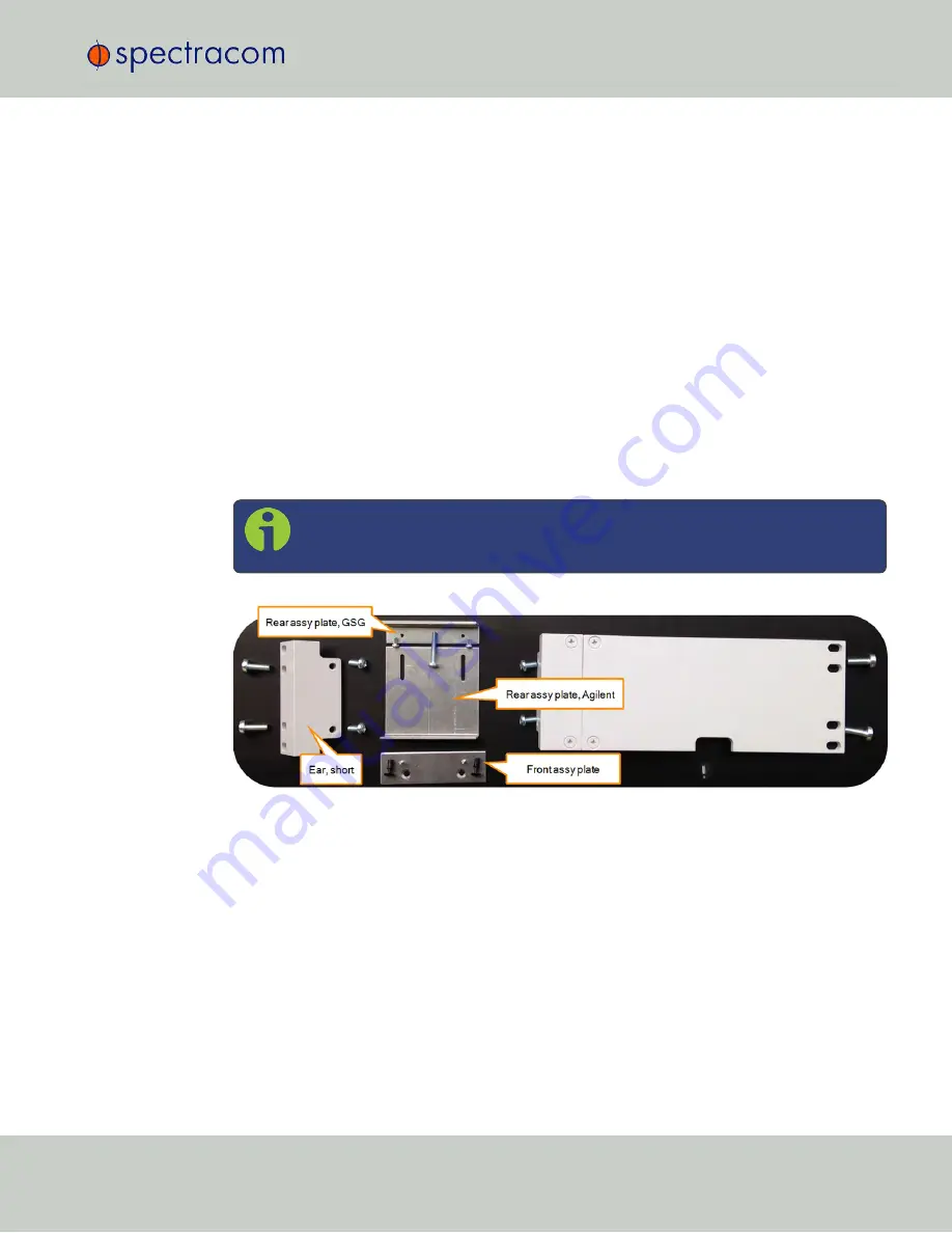
Figure 2-7:
22/04 Rack-mount kit
In order to prepare the GSG unit for rack mount installation, the housing needs to be opened,
in order to remove the bottom feet (otherwise the assembly will not fit in a 2U slot.) The same
may be necessary for the Agilent unit – follow the manufacturer's instructions.
1.
After making sure that the power cord has been unplugged, carefully turn the GSG unit
upside down.
2.
Temporarily remove the two
rear feet
by loosening their screws.
3.
Remove the four
housing screws
and plugs (if present) at the side panels, and discard
them.
4.
Grip the front panel with one hand, while pushing at the rear with the other hand. Pull
the unit out of its housing.
2.3 Mechanical Installation
CHAPTER
2
•
User Manual GSG-5/6 Series
Rev.
26
19
Summary of Contents for GSG-5 series
Page 2: ......
Page 4: ...Blank page II User Manual GSG 5 6 Series...
Page 116: ...BLANK PAGE 3 6 Options Menu 100 CHAPTER 3 User Manual GSG 5 6 Series Rev 26...
Page 182: ...BLANK PAGE 4 9 Studioview Tasks 166 CHAPTER 4 User Manual GSG 5 6 Series Rev 26...
Page 368: ...BLANK PAGE 6 7 Revision History SCPI Guide 352 CHAPTER 6 User Manual GSG 5 6 Series Rev 26...


