Space-Ray ERP10 Installation, Servicing And Operating Instructions Download Page 20

Page 1

8

 of 

20

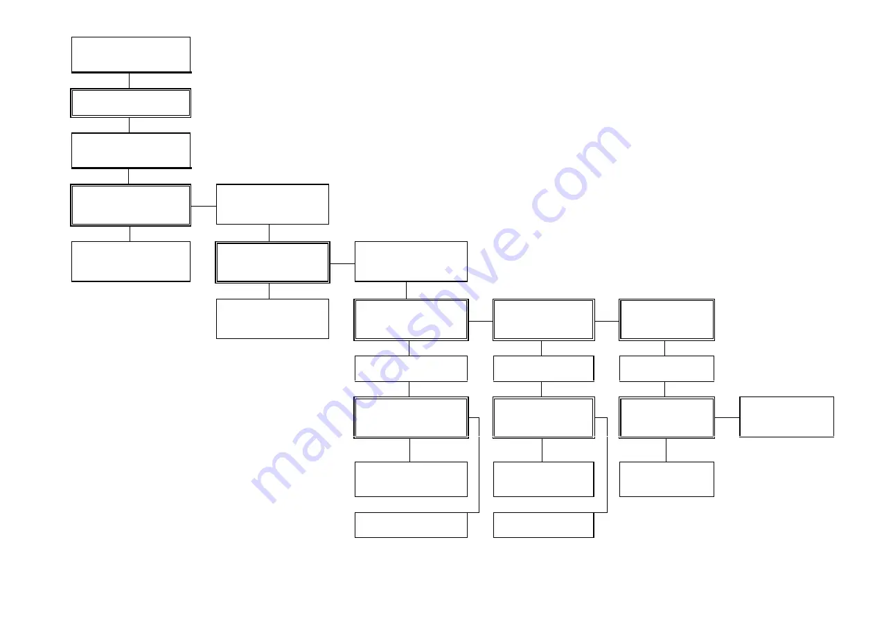
Check Gas & Electricity
supplies turned 'ON' 
Set Thermostat to 'MAX'

10.  FAULT  FINDING  CHART

Has Burner flame established

        NO

Check 230V present at Ignition
Control & 
circuit continuity


 YES

230V at Ignition Control &
circuit continuity correct

Check gas Supply pressure at
control valve test point 'IN'

        NO

 YES

Rectify electricity supply or
circuit continuity

Gas Supply pressure in
accordance with section 3.2.
of manual

Check gas Setting pressure
at Control valve test point
'OUT'

          NO

YES

YES

Rectify Gas Supply to the
appliance

Gas Setting pressure in
accordance with section 3.2
of manual

Is Ignition spark present at
Electrodes

Does Ignition Spark
cease when Burner
ignites

          NO

         NO

         NO

Adjust gas Setting pressure.
Check control valve operation

Check Spark Electrode
and circuit continuity

Check Flame Rod and
circuit continuity

YES

YES

YES

Gas Setting pressure &
control valve operation
correct.

Spark Electrode & circuit
continuity correct

Flame Rod and circuit
continuity correct

Replace Ignition Control

           NO

         NO

         NO

Replace Control Valve

Replace spark electrode &
rectify circuit continuity

Replace Flame Rod or
rectify circuit continuity

Replace Ignition Control

Replace Ignition Control

Summary of Contents for ERP10

Page 1: ...P SERIES MODELS ERP10 ERP20 ERP30 ERP40 ERP45 Gas Fired Products UK Ltd Chapel Lane Claydon Ipswich Suffolk IP6 0JL England Tel 01473 830551 Fax 01473 832055 E mail Info spaceray co uk www spaceray co...

Page 2: ......

Page 3: ...3 Checking Gas Pressure 12 5 4 Flame Supervision 12 6 Servicing 13 14 6 1 Ignition Electrode 13 6 2 Flame Sensor Probe 13 6 3 Venturi 13 6 4 Injector 13 6 5 Electrical Wiring 13 6 6 Reflector 14 7 Re...

Page 4: ...90kW Hs 17 43kW Hi Appliance Type A1 Appliance Cat II2H3P Gas Rate 1 96m 3 h 1 36kg h Adjusted For 2H G20 20mbar 3P G31 37mbar Setting Pressure 15 0mbar 25 0mbar Injector 2 x No 41 2 x No 52 Pre Injec...

Page 5: ...2 Pre Injector None None Electrical Supply 230V 50Hz 25W Fuse Externally 3A Dimensions L 0 673m W 0 848m H 0 197m Weight 20 36kg Gas Connection Rc Table 5 MODEL ERP45 N Heat Input 46 89kW Hs 42 25kW H...

Page 6: ...and suitable brackets are used Attach the chains or drop rods to the 4 holes located in the Side Frame Panels as shown in Fig 1 by use of M8 screws and nuts Providing at least 5mm closed link hooks a...

Page 7: ...Page 5 of 20 Fig 1 Disclaimer Valve and control assemblies will differ on European approved heaters...

Page 8: ...used and the pipework must be designed to achieve a gas supply pressure between the maximum and minimum valves stated above measured at the appliance inlet pressure test point A union service cock MUS...

Page 9: ...H 1 SWITCH 1 THERMOSTAT Fig 3 Notes The method of connection to the electrical supply must facilitate complete isolation and should preferably be via a fused double pole isolator having a constant sep...

Page 10: ...ET PLUG BASE ERP 10 20 30 40 45 SIDE FRAME PANEL VALVE G Y 3 3 5 Internal Wiring Diagram S I T Controls Fig 5 Fig 4 N L1 BK G Y BL BR 121110 9 8 7 6 5 4 3 2 1 G Y BL BR BL HT GR G Y 4 PIN BASE PLUG TE...

Page 11: ...penings 3 three times the vent height in the case of roof openings 3 4 1 2 Ventilation by Mechanical Evacuation Ventilation by mechanical evacuation is sufficient if 10m3 h of exhaust air per kW of op...

Page 12: ...ed to junction box attached to the Control Valve as follows Brown to terminal marked 1 Blue to terminal marked 2 Green Yellow to terminal marked 7 External fuse required 3 A See section 3 3 for electr...

Page 13: ...lenoid valve and ignition spark electrode will be de energised and the appliance Ignition Control will go to lockout condition 5 1 7 To repeat the ignition sequence it will be necessary to switch off...

Page 14: ...or below the Control Valve Category 2H gas type G20 natural setting pressure 15 0mbar Category 3P gas type G31 propane setting pressure 25 0mbar 5 3 2 3 In the event that the burner setting pressure i...

Page 15: ...y oxidised replace the electrode see section 7 1 6 1 4 Upon re assembly ensure that the HT lead connector is securely attached to the electrode 6 2 Flame Sensor Probe 6 2 1 Disconnect the grey flame s...

Page 16: ...probe by gently pulling the connector using pliers 7 2 2 Unscrew the two M4 screws securing the flame probe to the Side Frame Panel RH and withdraw the flame probe 7 2 3 After assembling a replacemen...

Page 17: ...located in the elbow flange and straight flange connectors are in sound condition and correctly positioned in the O ring grooves of the connectors 7 7 Reverberatory Screen 7 7 1 Remove the wire ties f...

Page 18: ...Injector No 52 LPG 4262 8 OPERATING INSTRUCTIONS 8 1 Direct Burner Spark Ignition Models 8 1 1 Turn on the gas supply to the appliance 8 1 2 Set any time switch or thermostats to demand heat 8 1 3 Swi...

Page 19: ...n using LPG that the reverberatory screen is fitted 9 2 Conversion from cat 2H Natural Gas to cat 3P LPG Appliance with reverberatory screen 9 2 1 Carry out the instructions 9 1 1 to 9 1 4 above leavi...

Page 20: ...Rectify Gas Supply to the appliance Gas Setting pressure in accordance with section 3 2 of manual Is Ignition spark present at Electrodes Does Ignition Spark cease when Burner ignites NO NO NO Adjust...

Page 21: ...NOTES Page 19 of 20...

Page 22: ...Page 20 of 20 09 03 GB 602S...

Reviews: