background image


www.spswh.com

                                              787-504-9927 


SPSWH.com SP Blue Solo 80 installation manual Doc  


SP.


SP Blue Solo 80.E.2021.REV1.0 

11 

|


P a g e


1.


Ensure that all electrical connections are OFF, secure, and not exposed to elements or potential 
leaks.  

2.


If start up is during the day please ensure the collectors are covered so as not to introduce cold 
water into a hot collector. This could flash to steam cause scalding and damage to the system.  

3.


Open pressure relief valve to vent the storage tank to atmosphere.  

4.


Open the mains water line and begin filling the tank/collectors.  

5.


Once water starts coming out of pressure relief valve close valve and pressurise system.  

6.


Check each of the connections for leaks.  

7.


Remove covering from solar collectors.  

8.


Set mixing valve to desired temperature.  

9.


Turn electrical element on and set to desired temperature. (EL models only)  

10.


Ensure pressure relief valve is closed and is piped to a safe location as it may operate in over 
temperature conditions causing hot water to be expelled and high pressure. 

5.1.1


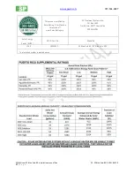
Expected Temperatures  

During normal operation, the system will experience temperature on the inlet and outlet approximately:   

-


Inlet temperatures to the collector avg 55°- 60°C (130°-140°F) 

-


Outlet temperatures to the storage tank avg 75° - 80° (165° - 175°F) 

5.2


Maintenance 

5.2.1


Solar Collector Cleaning 

The solar collectors do not require any maintenance; however, annual checks of the glass and 
connections should be made to ensure there are no leaks, cracks etc. At this time, the glass can be 
cleaned with a mild detergent if needed.   

5.2.1


Hardware 

It is recommended that all hardware is checked and tightened annually and/or after any sever weather.  

5.2.2


Scale prevention in solar collectors  

The solar collectors need to be flushed out using descaling solution once a year to ensure performance 
and reliability. This is due to the fact that potable water is being heated directly in the collector and the 
presence of CaCO3 (Calcium Carbonate) which precipitates out of water at temperatures above 50°C 
(122°F) and can reduce heat transfer, lower flow rates and cause system failure if not treated. Failure to 
follow these recommendations will void manufacturer warranty.  
 

1.


Isolate tank and shut off mains water. 

2.


Turn off electric connection to the system if applicable. 

3.


Cover the collectors to prevent heating descaling solution. 

4.


Remove the inlet and outlet connections to the collector using crescent wrench.  

5.


Using a descaling solution or other chemical for removing CaCO3 connect a hose to the inlet and 
outlet connections.  

6.


Using a small circulating pump circulate descaling solution through the collectors for minimum 
30 mins.  

Summary of Contents for Blue Solo 80

Page 1: ...0 Document SP BLUE SOLO 80 2021 REV1 0 Sustainable Products Treatment Systems Solar Water Heaters www spswh com Sales Service Antonio Davila 787 504 9927 Engineering Paul Pauze PE 787 438 0511 Mail PO Box 1653 Trujillo Alto PR 00977 Physical Address Carr 876 Km 1 2 Bo Cuevas Trujillo Alto PR ...

Page 2: ...Not included to Be Supplied by Installation Contractor 7 3 5 Performance 7 Installation Instructions 7 4 1 Orientation 7 4 2 Racking installation instructions 7 4 3 Solar Thermal System Installation Instructions 9 Startup Procedure 10 5 2 Maintenance 11 Operation Instructions 12 6 1 System Operation 12 6 2 Warranty 13 Appendix 15 7 1 OG 300 Label 15 7 2 Solar Tank Label 15 7 3 Freeze Protection La...

Page 3: ...an option that must be special ordered With an SUEF of 12 03 and Solar Fraction per Puerto Rico Supplementary of 93 the electrical element would rarely be needed even during sustained periods of cloud cover Making Puerto Rico Sustainable is our goal and with the purchase of the SP Blue Solo 80 or SP Blue Solo 80 E option you have made the right choice for your family and the environment Warnings T...

Page 4: ...and efficient The system is manufactured under license by SP Treatment Systems and consists of ONE 1 SP BlueWave 29 collector which have a gross area of 2 9m2 31 4 ft2 and a 300 L 80USG storage tank The E model Optional comes with a 3 5 kW auxiliary electric heating element installed in the solar storage tank to provide additional heat With between 95 to 100 of hot water needs met by the system se...

Page 5: ...www spswh com 787 504 9927 SPSWH com SP Blue Solo 80 installation manual Doc SP SP Blue Solo 80 E 2021 REV1 0 5 P a g e 3 1 System Diagram Figure 3 System diagram ...

Page 6: ...ptional 3 5 kW Electrical heating element and thermostat for E models only 1 a 3 5 electric heating element model 107511 1016 b Thermostat model 108809 1017 c Anode model 108803 0 d Rubber Flange model 100506 875 e Tube material incoloy 800 f 8 5 mm diameter with 298 mm protruding into the tank g Max current 20A 240VAC 1ɸ h Temperature range 10 85 C 50 185 F i Overload or Overcurrent protection of...

Page 7: ...em has a solar fraction of 93 of the hot water produced by this system will be provided by the sun See the Energy Start certificate for performance details Installation Instructions 4 1 Orientation The solar thermal system shall be positioned with collectors facing due south whenever possible It is recommended that the slope of the collectors be equal to that of the latitude i e in Puerto Rico the...

Page 8: ...n to ensure the location selected for installation can handle this load as well as the weight of installers and installation equipment It is recommended that the installer review local code and contact the local building department for confirmation of the structural integrity of any installation location It is also recommended that the homeowner consult with their insurance provider and inform the...

Page 9: ...led to prevent damage from the elements This can be a wrap or paint or other means to protect the installation from the elements specifically moisture and UV 4 3 2 Safety Relief Valve Temperature Pressure Safety relief valve dis charge pipes shall be of rigid pipe that is approved for the temperature of the system The discharge pipe shall be the same diameter as the safety or relief valve outlet S...

Page 10: ...e system Failure to install the pressure regulator valve can result in pressures exceeding warranty of the components Ensure Pressure is set below system limits As seen in the system diagram in Section 3 1 4 3 8 Drain Valve A drain valve should be installed in the system for ease of servicing Location of the drain valve should be at the lowest point in the system As seen in the system diagram in S...

Page 11: ...ratures to the storage tank avg 75 80 165 175 F 5 2 Maintenance 5 2 1 Solar Collector Cleaning The solar collectors do not require any maintenance however annual checks of the glass and connections should be made to ensure there are no leaks cracks etc At this time the glass can be cleaned with a mild detergent if needed 5 2 1 Hardware It is recommended that all hardware is checked and tightened a...

Page 12: ...he electrical breaker be turned off to conserve power If the system is going to be left unattended for longer than one month with no use it is recommended to turn off the electric element and drain the system This can be done by turning off the mains water and opening the drain valve Danger When draining the system water could be very hot Caution must be taken when opening drain valve and touching...

Page 13: ...ezing temperatures See decommissioning section for more details on how to drain the system Danger When draining the system water could be very hot Caution must be taken when opening drain valve and touching pipes Warning Please exercise caution when turning on off electrical power If unsure call qualified electrical contractor 6 2 Warranty The system is covered by a manufacturers warranty in accor...

Page 14: ...6 2 4 Warranty Remarks Any damage to the glass must be assessed and remedied immediately such as cracks etc or else the potentials for damage to the absorber and loss of system performance Any superficial discolouration of the absorber may reduce panel efficiency slightly but will not damage the system and is not cause for concern Any discolouration or corrosion of the racking and support base doe...

Page 15: ...SRCC 10002144 OG 100 X1 collectors Heat transfer fluid and concentration range Fresh Water Storage tank volume 300 L 80 USG Expansion tank volume NA Relief valve specification and setpoint 93 C 99 C 850 kPa 199 F 210 F 123 PSI Maximum water supply pressure 8 bar 116 PSI Maximum solar loop pressure 16 bar 232 PSI Backup energy rating Include phase volts amps 3500 W 1P 240V 20A Installation date fie...

Page 16: ...nstallation manual for how to drain the system 7 4 Hot Fluid Label DANGER Fluid could be discharged at high temperatures or pressures or both Fluids shall not be used that would change the original classification of this system Unauthorized alterations to this system could result in a health hazard or hazardous conditions 7 5 Electrical Hazard Label DANGER This system contains electrical connectio...

Page 17: ...0 17 P a g e This product certified by Solar Rating Certification Corporation www Solar Rating org SP Treatment Systems Inc P O Box 1653 Trujillo Alto 00977 Puerto Rico SPSWH COM Solar Energy Factor SUEF SRCC Cert No Model No 12 09 30004362 SP Blue Solo 80 SP Blue Solo 80E The installed system is marked above ...

Page 18: ...allation manual Doc SP SP Blue Solo 80 E 2021 REV1 0 18 P a g e Please note this table MUST be on a single page with no other content If the SRCC certification changes due to private labeling then the updated table must be inserted here 7 6 Electrical Diagram ...

Reviews: