background image

South Bend Tools

For Machines Mfd. Since 12/21

Model SB1007

-19-

P R E P A R A T I O N

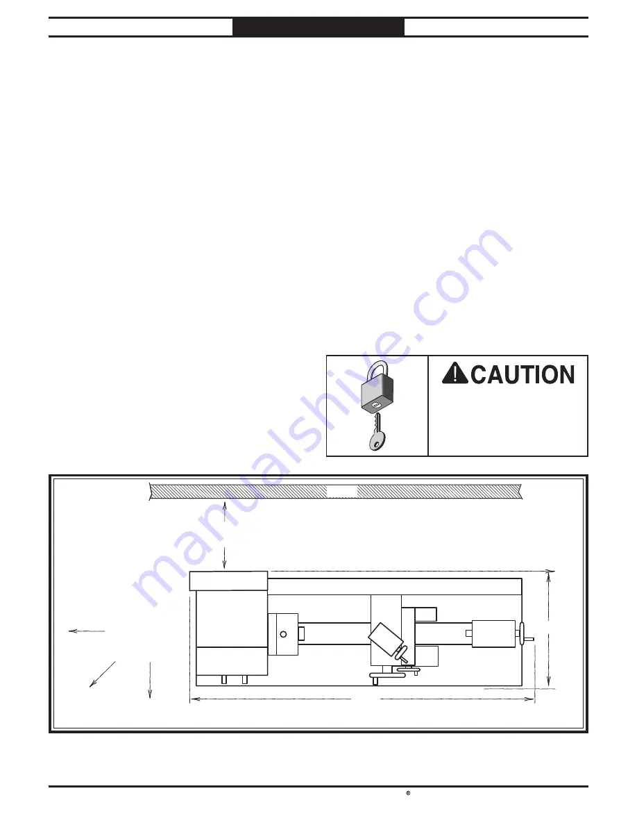
Keep 

Workpiece 

Loading Area 

Unobstructed

Wall

30" Minimum

for Maintenance

61"

28

1⁄2

"

Not to Scale

Figure 

Figure 11. SB1007 working clearances.

. SB1007 working clearances.

Physical Environment

Electrical Installation

Lighting

Weight Load

Space Allocation

Weight Load

Refer to the Machine Specifications for the 

weight of your machine. Make sure that the 

surface upon which the machine is placed will 

bear the weight of the machine, additional 

equipment that may be installed on the machine, 

and the heaviest workpiece that will be used. 

Additionally, consider the weight of the operator 

and any dynamic loading that may occur when 

operating the machine.

Space Allocation

Consider the largest size of workpiece that will 

be processed through this machine and provide 

enough space around the machine for adequate 

operator material handling or the installation 

of auxiliary equipment. With permanent 

installations, leave enough space around 

the machine to open or remove doors/covers 

as required by the maintenance and service 

described in this manual.

Physical Environment

The physical environment where your machine 

is operated is important for safe operation and 

longevity of parts. For best results, operate this 

machine in a dry environment that is free from 

excessive moisture, hazardous or flammable 

chemicals, airborne abrasives, or extreme 

conditions. Extreme conditions for this type 

of machinery are generally those where the 

ambient temperature is outside the range of 41°–

104°F; the relative humidity is outside the range 

of 20–95% (non-condensing); or the environment 

is subject to vibration, shocks, or bumps.

Electrical Installation

Place this machine near an existing power 

source. Make sure all power cords are protected 

from traffic, material handling, moisture, 

chemicals, or other hazards. Make sure to leave 

access to a means of disconnecting the power 

source or engaging a lockout/tagout device.

Lighting

Lighting around the machine must be adequate 

enough to perform operations safely. Shadows, 

glare, or strobe effects that may distract or 

impede the operator must be eliminated.

Children or untrained 

people may be seriously 

injured by this machine. 

Only install in an access 

restricted location.

Location

Summary of Contents for SB1007

Page 1: ...e 11 14 A Tradition of Excellence South Bend Tools MODEL SB1007 HEAVY 10 10 X 30 GEARHEAD LATHE OWNER S MANUAL Shown with Optional SB1035 Stand 177335 April 2016 by South Bend Tools Revised December 2...

Page 2: ...on is a process that happens through training and experience If you are not an experienced operator of this type of machinery read through this entire manual then learn more from an experienced operat...

Page 3: ...rview 28 Installation Removal Devices 29 Chuck Installation 29 Chuck Removal 31 Scroll Chuck Clamping 31 Changing Jaw Set 32 Tailstock 33 Carriage Slide Locks 37 Compound Rest 38 Four Way Tool Post 38...

Page 4: ...join the ranks of some very famous and important customers such as Henry Ford who used his South Bend lathe to help him change the world Capabilities This Heavy 10 Gearhead Lathe is built for daily u...

Page 5: ...Button Power Power Lamp Lamp Master Power Master Power Switch Switch D1 4 Camlock D1 4 Camlock Spindle Spindle 3 Jaw Scroll 3 Jaw Scroll Chuck Chuck 4 Way 4 Way Tool Post Tool Post Compound Rest Comp...

Page 6: ...d H Stop Button Stops all machine functions Twist clockwise to reset I Feed Direction Lever Selects carriage or cross slide for power feed operations The spindle must be completely stopped before usin...

Page 7: ...ges disengages half nut for threading operations M Carriage Handwheel Moves carriage along bed N Cross Slide Handwheel Moves cross slide toward and away from workpiece O 4 Way Tool Post Mounts up to f...

Page 8: ...for threading or the feed rod for power feed operations The rotational speed of these components depends not only on the end gear configuration but the spindle speed as well End Gears Figure Figure 7...

Page 9: ...h x Width x Height 63 x 34 x 30 in Must Ship Upright Yes Electrical Power Requirement 240V Single Phase 60 Hz Full Load Current Rating 6 2A Minimum Circuit Size 15A Connection Type Cord Plug Power Cor...

Page 10: ...in Tailstock Taper MT 3 Tailstock Barrel Diameter 1 574 in Threading Info Number of Longitudinal Feeds 15 Range of Longitudinal Feeds 0 0018 0 0128 in rev Number of Cross Feeds 15 Range of Cross Feed...

Page 11: ...Gearbox Capacity 0 37 qt Gearbox Fluid Type ISO VG32 eg Grizzly T23963 Mobil DTE Light Other Country of Origin Taiwan Warranty 2 Years Serial Number Location ID Label ISO 9001 Factory No Certified by...

Page 12: ...e as follows Death or catastrophic harm WILL occur Moderate injury or fire MAY occur Death or catastrophic harm COULD occur Machine or property damage may occur Basic Machine Safety Owner s Manual All...

Page 13: ...d by verifying that all fastening devices are properly secured and items attached to spindles have enough clearance to safely rotate Chuck Keys or Adjusting Tools Tools used to adjust spindles chucks...

Page 14: ...ring installation and removal protect your hands and precision bed ways by using a chuck cradle or piece of plywood over the bed ways Long Stock Safety Long stock can whip violently if not properly su...

Page 15: ...es coming loose at high speeds and striking the operator or bystanders with deadly force To reduce the risk of this hazard read and understand this document and seek additional training from an experi...

Page 16: ...y Metal Protectant Oil Workbench Stand Mounting Hardware As Needed Precision Level The purpose of the preparation section is to help you prepare your lathe for operation The list below outlines the ba...

Page 17: ...it To reduce the risk of these hazards avoid overloading the machine during operation and make sure it is connected to a power supply circuit that meets the requirements in the following section Full...

Page 18: ...ther the tool is properly grounded If you ever notice that a cord or plug is damaged or worn disconnect it from power and immediately replace it with a new one Extension Cords Minimum Gauge Size 14 AW...

Page 19: ...materials while unpacking or they are pre installed at the factory Figure Figure 9 Main inventory Main inventory A A C C B B Main Inventory 1 Figure 9 Qty A 3 Jaw Chuck 6 w Back Plate 1 B Outside Jaw...

Page 20: ...ed surface to make sure they will not damage it Basic steps for removing rust preventative 1 Put on safety glasses and disposable gloves 2 Coat all surfaces that have rust preventative with a liberal...

Page 21: ...e doors covers as required by the maintenance and service described in this manual Physical Environment The physical environment where your machine is operated is important for safe operation and long...

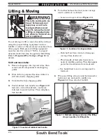
Page 22: ...Push tailstock lock handle see Figure 12 forward toward headstock and move tailstock to end of bedway Then retighten lock handle 5 To further balance the load move carriage next to tailstock as follo...

Page 23: ...stock headstock Note See Figure 16 for an example photo of lifting the lathe with the straps positioned as instructed above Figure Figure 16 Example photo of lifting lathe with straps Example photo of...

Page 24: ...spaper is placed under one end of the level See the figure below for an example of a high precision level Figure Figure 17 Example of a precision level Example of a precision level The base of this ma...

Page 25: ...l Lubrication GEARBOXES MUST BE FILLED WITH OIL OIL MAY NOT BE SHIPPED WITH MACHINE Refer to Lubrication Section for Correct Oil Type The headstock and quick change gearbox must have the proper amount...

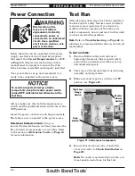
Page 26: ...st Power Connection Electrocution or fire may occur if lathe is ungrounded incorrectly connected to power or connected to an undersized circuit Use a qualified electrician to ensure a safe power conne...

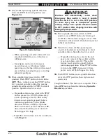
Page 27: ...ver to neutral middle position see Figure 22 DO NOT use jog button to help mesh gears when changing spindle speeds or speed range Doing so could damage gears and connected components 9 To ensure carri...

Page 28: ...by twisting it clockwise then remove end gear cover This activates a safety switch that should prevent lathe from starting 15 Stand away from all the exposed gears on side of headstock and attempt to...

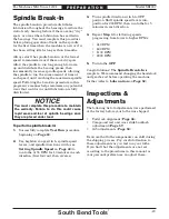
Page 29: ...ure distributes lubrication throughout the bearings to reduce the risk of early bearing failure if there are any dry spots or areas where lubrication has settled in the bearings You must complete this...

Page 30: ...nd do additional research outside of this manual by reading how to books trade magazines or websites To complete a typical operation the operator does the following 1 Examines workpiece to make sure i...

Page 31: ...straight into spindle cam holes Important Avoid inserting studs by pivoting them in from an angle or rotating the spindle This can damage studs or spindle cam holes Installation Removal Devices Becau...

Page 32: ...s Camlock Spindle 2 Piece Direct Mount Camlock Chuck Marks for Chuck Reassembly Chuck Halves Spindle Chuck Registration Marks Registration Marks Lightly stamp registration marks across the mating seam...

Page 33: ...nstable Workpiece Shallow Bar Stock Outside Safer Use Jaw Grip Figure Figure 30 Camlock is fully loosened when cam line is Camlock is fully loosened when cam line is aligned with spindle mark aligned...

Page 34: ...nd abrasives 6 Rotate chuck key clockwise until you see tip of outer scroll gear lead thread about to enter a jaw guide see below 7 Insert jaw 1 into jaw guide and hold jaw against scroll gear 8 Rotat...

Page 35: ...he spindle The entire tailstock can be repositioned and locked in place along the length of the bed An independently controlled offset adjustment allows the upper part of the tailstock to move perpend...

Page 36: ...oling Types of tapered arbors and tooling Open Open End End Solid Solid End End Screw Screw End End Tang Tang End End Figure Figure 37 Example photos of MT 3 tools being Example photos of MT 3 tools b...

Page 37: ...ure that no lint or oil remain on tapers Note This will ensure that tool will seat properly and reduce runout 3 With a firm quick motion insert tool into quill Check to see if it is firmly seated by a...

Page 38: ...To Spindle Centerline This is an essential adjustment that should be verified or performed each time the tailstock is used to turn concentric workpieces between centers or immediately after offsettin...

Page 39: ...the distance of the taper Looking down from above Figure Figure 43 Adjust tailstock toward back of lathe Adjust tailstock toward back of lathe If test stock is thicker at tailstock end move tailstock...

Page 40: ...at the operator or bystanders with great force DO NOT extend a cutting tool more than 2 5 times the width of its cross section e g 2 5 x 0 5 1 25 2 Rotate rest to desired angle indicated by scale at...

Page 41: ...s slide to the tip of the center Adjust the cutting tool height so it is the same distance above the cross slide as the tailstock center Make a facing cut on a piece of round bar stock If tool is abov...

Page 42: ...ad graduated dial with 0 001 0 025mm increments One full revolution of the handwheel moves the slide 0 50 1 25mm Figure Figure 50 Carriage handwheel controls Carriage handwheel controls Compound Compo...

Page 43: ...Determine the best spindle speed for the cutting task and 2 configure the lathe controls to produce the required spindle speed Determining Spindle Speed Many variables affect the optimum spindle speed...

Page 44: ...RPM 1 Press STOP button and make sure spindle has completely stopped Additionally the books Machinery s Handbook or Machine Shop Practice and some internet sites provide excellent recommendations for...

Page 45: ...ions the carriage can be driven by the leadscrew However this section only covers the use of the power feed option for the carriage and cross slide components for non threading operations To learn how...

Page 46: ...HES Figure Figure 60 Feed rate chart Feed rate chart Using the controls on the lathe follow along with the example below to better understand how to set the lathe for the desired power feed rate C Fee...

Page 47: ...nd the lever will engage End Gears The end gears on this lathe can be configured according to the operation to be performed power feed and inch or metric threading The operation you choose will determ...

Page 48: ...ew gears do not overtighten cap screws They simply hold gears in place Overtightening could hinder gear rotation 5 Install middle gear on upper slot see Figure 62 The gear bolts directly onto support...

Page 49: ...R 2 Locate 13 TPI on additional inch thread chart see Figure 64 on end gear cover 3 Install 40T 60T 90T and 95T gears as instructed in End Gears on Page 45 Note The 65T gear called out in the above di...

Page 50: ...lf nut lever The operator then returns the carriage for the next pass and re engages the half nut using the same thread dial setting to resume cutting When threading we recommend using the slowest spe...

Page 51: ...6 ANY POSITION NON NUMBERED POSITION 12 20 28 36 44 52 76 5 4 3 2 1 8 7 6 6 10 14 18 22 26 38 54 NUMBERED POSITION 8 16 24 32 40 48 56 64 72 80 96 112 128 TPI 5 4 3 2 1 8 7 6 5 7 9 11 13 19 27 NUMBERE...

Page 52: ...s 56th edition is an exact reprint from 1966 Well illustrated with vintage photos and drawings this 128 page book is written specifically about the care and operation of a metal lathe SB1365 Way Oil E...

Page 53: ...tartup Ensure carriage lock screw is loose Always disconnect lathe from power before performing maintenance or serious personal injury may result Daily After Operations Press STOP button and turn mast...

Page 54: ...reservoir has the proper amount of oil when the oil level sits approximately halfway in the sight glass Adding Oil To add oil remove the headstock top plate shown in Figure 78 Tools Needed Qty Hex Wre...

Page 55: ...oir until oil level is visible at halfway point in sight glass then replace headstock top plate 10 Pivot end gear support arm upward until gears mesh refer to End Gears on Page 45 then retighten suppo...

Page 56: ...Figure 81 Bedways and leadscrew Bedways and leadscrew Leadscrew Leadscrew Bedways Bedways Ball Oilers Oil Type Mobil DTE Light or ISO 32 Equivalent Oil Amount 1 or 2 Squirts Fill Lubrication Frequenc...

Page 57: ...Lower Middle Gear Middle Gear Top Gear Top Gear Figure Figure 83 Cross slide ball oilers Cross slide ball oilers D D Handling Care Clean and lubricate any gears you install or change Be careful during...

Page 58: ...s are open to the air can experience bleaching discoloring of paint or yellowing of clear plastic guards If decommissioning this lathe use the steps in this section to ensure that it remains in good c...

Page 59: ...ash is the amount of free play felt in the handwheel when changing direction of rotation This can be adjusted on the compound rest and cross slide leadscrews and the amount of backlash can be observed...

Page 60: ...adjusting the gib screws is to remove sloppiness or play from the ways without over adjusting them to the point where they become stiff and difficult to move In general loose gibs cause poor finishes...

Page 61: ...und rest movement is acceptable 5 Hold set screws in place and retighten jam nuts Cross Slide Gib Tools Needed Qty Flat Head Screwdriver 2 1 To adjust cross slide gib 1 DISCONNECT LATHE FROM POWER 2 T...

Page 62: ...r to the drive pulley Because the molded teeth in the belt fit together with matching teeth in the pulley the timing belt will not slip unless the belt teeth become overly worn or belt tension is over...

Page 63: ...DISCONNECT LATHE FROM POWER 2 Remove end gear cover 3 Loosen four motor mount hex bolts see Figure 93 on previous page slide motor up and remove belt Note Loose pulleys impact transmission of power fr...

Page 64: ...trol box at fault 8 Inspect inverter control box replace 9 Motor at fault 9 Test repair replace 10 Spindle rotation switch at fault 10 Test repair replace Machine stalls or is underpowered 1 Machine u...

Page 65: ...ge 57 4 Bedways are dry 4 Lubricate bedways and handles Cutting tool or lathe components vibrate excessively during cutting 1 Tool holder not tight enough 1 Check for debris clean and retighten 2 Cutt...

Page 66: ...iage stop position and adjust as necessary see Page 40 7 Gibs are too tight 7 Loosen gib screw s slightly see Page 58 Workpiece is tapered 1 Headstock and tailstock are not properly aligned with each...

Page 67: ...results including serious injury or fire Motor Wiring The motor wiring shown in these diagrams is current at the time of printing but it may not match your machine Always use the wiring diagram insid...

Page 68: ...e Induction Motor Control Panel Viewed from Behind Circuit Breaker Contactor Jog Button Inverter AVC AVC 1 Highly Z15G1318 Limit Switch Direction Switch Emergency Stop Button Mou Jen M6L AS550R Power...

Page 69: ...Mfd Since 12 21 Model SB1007 67 E L E C T R I C A L Electrical Component Pictures Figure Figure 96 Electrical box Electrical box Figure Figure 97 Control panel Control panel Figure Figure 98 Motor ju...

Page 70: ...9 1 11 12 15 15 1 15 2 16 16 1 16 2 16 2 17 18 19 20 21 17 1 21 1 22 23 24 25 92 27 28 29 30 31 32 33 34 35 36 26 37 38 39 40 41 42 43 44 45 46 51 52 53 54 55 56 56 57 58 59 62 63 64 65 66 67 68 69 70...

Page 71: ...7 TAPERED ROLLER BEARING 32009 FAG 17 1 PSB1007017 1 EXT RETAINING RING 12MM 68 PSB1007068 OIL SIGHT GLASS 3 8 NPT 18 PSB1007018 GEAR 32T 69 PSB1007069 HEX NUT M10 1 5 19 PSB1007019 GEAR 30T 70 PSB100...

Page 72: ...114 115 116 117 118 119 162 120 197 198 121 122 123 124 125 126 127 162 128 129 130 131 132 133 134 135 136 137 138 139 140 141 142 143 144 199 145 146 147 148 149 150 151 152 153 154 155 156 157 158...

Page 73: ...7123 GEAR 35T 25T 32T 29T 24T 173 PSB1007173 OIL SEAL 30 X 22 X 4 124 PSB1007124 GEAR 38T 29T 19T 174 PSB1007174 ROLL PIN 4 X 25 125 PSB1007125 GEAR 42T 175 PSB1007175 EXT RETAINING RING 10MM 126 PSB1...

Page 74: ...48 223 221 283 284 263 246 246 1 246 2 246 3 246 4 246 5 244 245 247 209 210 275 276 238 232 285 273 231 240 230 229 239 215 282 205 202 246 6 277 241 264 219 208 249 213 281 268 203 228 207 270 214 2...

Page 75: ...SB1007263 KEY 6 X 6 X 40 222 PSB1007222 PIVOT SHAFT BRACKET 264 PSB1007264 KEY 3 X 3 X 8 223 PSB1007223 MOTOR MOUNT 266 PSB1007266 STEEL BALL 6MM 224 PSB1007224 MICROMETER CARRIAGE STOP 267 PSB1007267...

Page 76: ...des 301 302 303 304 305 306 307 308 309 310 311 312 362 313 314 315 316 317 363 318 319 364 365 366 320 321 322 323 324 325 326 327 328 329 307 331 332 367 333 334 334 335 336 337 338 339 340 341 342...

Page 77: ...M8 1 25 X 10 315 PSB1007315 TOOL POST SHAFT 349 PSB1007349 COMPOUND SLIDE HW KNOB M6 1 316 PSB1007316 COMPOUND SLIDE LEADSCREW 350 PSB1007350 COMPOUND SLIDE HW HANDLE M6 1 X 10 317 PSB1007317 COMPOUN...

Page 78: ...LL LEADSCREW 423 PSB1007423 EXT RETAINING RING 25MM 406 PSB1007406 QUILL LEADSCREW NUT 424 PSB1007424 LOCK NUT M12 1 75 407 PSB1007407 CLAMP BOLT M12 1 75 X 35 425 PSB1007425 QUILL LOCK BOLT M6 1 X 70...

Page 79: ...PSB1007507 LIMIT SWITCH AVC AVC 1 HIGHLY Z15G1318 502 PSB1007502 POWER LAMP MOU JEN M6L AS550R 22MM 508 PSB1007508 CONTACTOR TECO CU 11 220V 503 PSB1007503 SPEED SWITCH AUSP CS 2221 22MM 509 PSB100750...

Page 80: ...618 PSB1007618 GEAR DRIVE SHAFT 605 PSB1007605 CHANGE GEAR 70T 619 PSB1007619 TAPERED SPINDLE SLEEVE MT 5 MT 3 606 PSB1007606 CHANGE GEAR 65T 620 PSB1007620 BACK PLATE 607 PSB1007607 CHANGE GEAR 60T 6...

Page 81: ...erious impact injuries or death Always use slow spindle speeds with large or non concentric workpieces Never exceed chuck RPM rating WARNING WARNING INJURY HAZARD Always remove chuck key from chuck af...

Page 82: ...07 Fluid Capacities WARNING INJURY SHOCK HAZARD To avoid shock disconnect power before opening this door WARNING PINCH ENTANGLEMENT HAZARD Disconnect machine from power before opening this cover South...

Page 83: ...of any domestic or foreign government industry or authority In no event shall South Bend s liability under this warranty exceed the original purchase price paid for this machine Any legal actions brou...

Page 84: ...southbendtools com Printed In U S A MN16349...

Reviews: